
Introduction
Application engineers sometimes encounter control loops having multiple control valves. The reasons for incorporating two or more valves into the loop can be any of the following:
- provide more precise flow control via a small valve while using a larger valve to keep the small valve in control range.
- maximize overall efficiency by minimizing the position of the least efficient control valve.
- control a variable with two or more control valves in a split-range scheme.
Split-range control was described in a previous functional specification as one valve moving through a portion of the controller output range while the other valve moves through a different portion of the output range. The relative positions of the two valves are always fixed. In this functional specification, the other two types of multiple control valve strategies are described. Unlike split-range, the relative positions are not fixed.
In the case of precision flow control, one valve is smaller and therefore provides more precise control, while the other larger valve is used to handle load changes and keep the smaller valve in control. This arrangement is sometimes called “big valve – little valve”.
In the case of efficiency maximization, the two valves are needed to provide both fast control response and economical operation. This strategy usually involves maximizing the position of the control valve versus speed. Typical examples are air damper / forced draft fan speed, and flow control valve / pump VFD speed.
This document describes the precision flow control and efficiency maximization strategies, and how to implement them in a Foxboro I/A system.
Precision Flow Control
Natural Gas Supply Pressure Control Example
Natural gas supply pressure control is a very simple example of the big valve – little valve strategy. Figure 1 shows a typical control scheme.
The pressure controller (PC) adjusts the little valve (1” in this case). A valve position controller (ZC) looks at the little valve position and adjusts the big valve (2” in this case) to keep the little valve in control range. The ZC is typically a “gap” controller in which no control action occurs within the gap (e.g., 20-40% little valve position.
For example, if the little valve is above the gap, the ZC gradually opens the big valve to force the PC to close the little valve, thus bringing it back into control range.

Big Valve – Little Valve Strategy for SRU
The big valve – little valve strategy often utilizes two flow controllers:
- One controller with a small flow range and small control valve.
- Another controller with a larger flow range and larger control valve.
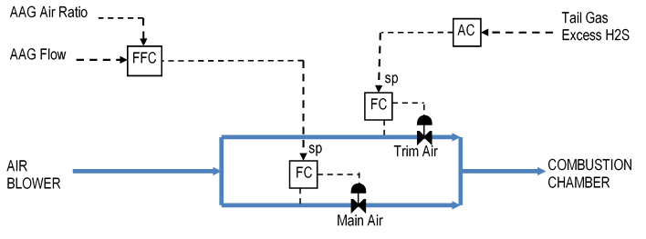
Figure 2 shows this strategy implemented for a Sulfur Recovery Unit (SRU). The primary control objective is to maintain a 2-to-1 ratio of H2S moles to SO2 moles in the reactors to conform to the stoichiometry of the reaction, thus maximizing sulfur recovery. Combustion air flow is adjusted to meet the control objective.
However, the only location where the composition can be analyzed is the tail gas at the end of the unit. Therefore, an analyzer measures the tail gas H2S and SO2 content and the calculated excess moles of H2S (= H2S – 2SO2) becomes the input to an analyzer controller (AC).
Precise control over the combustion air flow is important in this process because of the extreme sensitivity of the excess H2S calculation to combustion air flow. Therefore, the air flow is split into main air containing a control valve designed for full air flow (i.e., big valve) and trim air containing a control valve designed for a small fraction of the total air flow (i.e., little valve).
The AC is cascaded to the trim air flow controller. The amine acid gas (AAG) feed rate to the SRU is sent to a ratio controller (FFC), whose output is cascaded to the main air flow controller. The FFC provides feed-forward control for load changes, in this case AAG rate, which occur all too often in a typical refinery.
Valve Position Control Example
The previous example requires operator intervention whenever the trim air valve becomes too far open or closed. The operator must very carefully adjust the ratio entry on the FFC to bring the trim air valve back into a good control range.
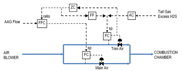
This manual operation can be automated to provide a smoother adjustment of the AAG ratio. Figure 3 shows a valve position controller (ZC) looking at the trim air valve position and adjusting the AAG ratio to keep the trim air valve in control range. The ZC is typically a “gap” controller in which no control action occurs within the gap (e.g., 20-40% trim air position).
ZC adjustments to the AAG ratio are likely to disturb the tail gas analyzer, which will respond slowly to main air rate changes. Therefore, feed forward (FF) has been added to Figure 3 to automatically adjust the trim air for any changes that the ZC makes to the main air. For example, when the ZC makes a ratio change that results in a 1 SCFH change in the main air, the FF makes a 1 SCFH change to the trim air in the opposite direction.
Feedforward techniques are discussed in a separate Functional Specification on the SAS website. The website also has a functional specification covering SRU Process Controls, which includes a combustion air control scheme similar to Figure 3.
Efficiency Maximization
Forced Draft Fan Control Example
Some fired heaters have a forced draft (FD) fan that supply combustion air to the heater. The air flow can be controlled by adjusting either the fan speed or a damper position. In a few cases, the FD fan has both available for manipulation (see Figure 4).
The air flow controller (FC) adjusts the damper. An auto-manual station (HC) adjusts the fan speed. A valve position controller (ZC) looks at the damper position and adjusts the fan speed via the auto-manual station to keep the damper in control range. The ZC is typically a “gap” controller in which no control action occurs within the gap. The gap must be set high (e.g., 40-50% damper position) to minimize the speed.
For example, if the damper position is below the gap, the ZC reduces the fan speed to force the FC to open the damper. This results in a more efficient operation.

VFD Pump Control Example
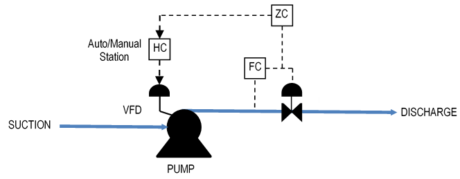
The flow through pumps with a variable frequency drive (VFD) can be controlled by adjusting either the pump speed or a control valve. Figure 5 shows a typical control scheme.
The flow controller (FC) adjusts the control valve. An auto-manual station (HC) adjusts the pump speed. A valve position controller (ZC) looks at the control valve position and adjusts the pump speed via the auto-manual station to keep the control valve in control range. The ZC is typically a “gap” controller in which no control action occurs within the gap. The gap must be set high (e.g., 40-50% damper position) to minimize the speed.
For example, if the control valve is below the gap, the ZC reduces the pump speed to force the FC to open the control valve. This results in a more efficient operation.
Foxboro I/A Implementation
Application Components
The SRU big valve – little valve application shown in Figure 3 is best handled by the configuration detailed in the functional specification for SRU Process Controls (see SAS website). The other examples are simpler and have similar configurations.
A typical precision flow control application contains the following blocks:
- PIDA flow controller (FC001 in Figure 6).
- PIDA valve position controller (ZC001 in Figure 6).
- BIAS auto-manual speed controller (HC002 in Figure 6).

Flow Controller FC001
Flow controller FC001 manipulates the little valve via ROUT block FV001. FC001 has the following connection:
BCALCI = :FV001.BCALCO
Its output should be connected to FV001.MEAS.
Valve Position Controller ZC001
Valve position controller ZC001 should have the following connections:
MEAS = :FC001.OUT
BCALCI = :HV002.BCALCO
HOLD = :FC001.MA.~ (ZC should go into hold when FC is not in automatic)
AUTSW = :ZC001.AUTSW.1 (Lock in automatic)
LOCSW = :ZC001.LOCSW.1 (Lock in local)
ZC001 parameters must be set as follows:
SPT = center of controllable range
MODOPT = 4 (PI – must have proportional for gap control to work)
HSCI1 = 100
LSCI1 = 0
PBAND = weak (note: control action should be mostly integral)
NONLOP = 1
HZONE = portion of gap below SPT (e.g., 5% and a SPT of 60% means low end of gap at 55%)
LZONE = portion of gap above SPT (e.g., 5% and a SPT of 60% means high end of gap at 65%)
KZONE = 0.0 (no control action inside of gap)
ZC001 output should be connected to HC002.MEAS.
Bias Controller HC002
Bias controller HC002 manipulates the big valve via ROUT block HV002. HC002 has the following connections:
MEAS = :ZC001.OUT
BCALCI = :HV002.BCALCO
REMSW = :HC002.REMSW.1 (Lock in remote)
RBIAS = :HC002.RBIAS.0.0 (Lock to zero)
HC002 parameters must be set as follows:
HSCI1 = 100 (Same as range of ZC001 output)
LSCI1 = 0
KMEAS = 1.0
BTRKOP = 0
In manual, HC002 manipulates the big valve directly. In automatic, HC002 allows ZC001 to manipulate the big valve.
Block Execution Order
The block execution order is important to the proper functioning of the application:
- Flow controller (FC001)
- Valve position controller (ZC001)
- Bias controller (HC002)
- ROUT blocks for control valves (FV001 and HV002)