
Introduction
The PID controller is most effective when the response is proportional to the output. In fact, the “P” in PID stands for proportional. However, some variables do not respond at all proportionally. The best example of this non-proportionality, or nonlinearity, is pH.
pH is a measure of the acidity or basicity of an aqueous solution. A value of 7.0 means that the solution is neutral. A value below 7.0 is acidic and a value above 7.0 is basic. pH is defined via the following equation:
pH = -log10[H+] (1)
where:
[H+] = concentration of hydrogen ions.
As the equation indicates, a linear change in the hydrogen ion concentration results in a logarithmic, or highly nonlinear, change in pH. Therefore, the standard PID algorithm will have great difficulty controlling pH over any sizable range.
This document describes a pH control strategy and how to implement it in a Foxboro I/A system.
pH Linearization Equation
The following equation linearizes pH:
MEAS = SCALE * [10pH-14 – 10-pH] (2)
where:
SCALE = arbitrary scaling factor.
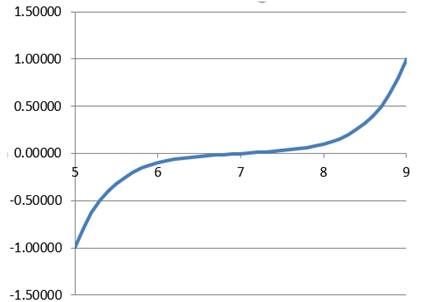
Figure 1 shows the linearized MEAS for an application in which pH is between 5.0 and 9.0 and the SCALE factor set to 100000. The linearized values range from -1.0 to +1.0.
Note: This linearization assumes no buffering of the pH, which can attenuate the non-linear response. If buffering is both present and consistent, then a titration can be used to determine the curve in Figure 1. However, most pH applications involve streams with widely varying compositions, so buffering is difficult to predict. Therefore, all we have is equation 2, which is a decent approximation of the response.
pH Control Strategy
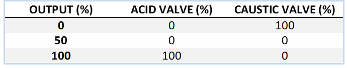
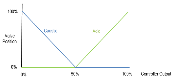
The recommended pH control strategy is illustrated in Figure 2. Acid or caustic is injected into a wastewater stream whose pH must be controlled before leaving the mixing tank. The pH measurement is linearized (AX) before entering the controller (AC). The acid and caustic are split-ranged (S/R) as shown in Table 1 and Figure 3. The V-shaped split range is necessary to prevent the simultaneous injection of both acid and caustic. Each valve is adjusted by a hand controller (HC) which sends the split-range calculation result to the valve when the HC is in automatic. The HC can be put into manual to adjust the valve independent of the split-range whenever necessary (e.g., valve stroking after maintenance).
In the Foxboro I/A control system, the BIAS block is used for the HC. It has the useful feature of ramping the valve to the split-range position after the HC is put into automatic. When the ramp is tuned properly, the transfer to automatic can be nearly bumpless.
It is unreasonable to expect the operators to enter the linearized setpoint to the controller. Therefore, the application should include a faceplate controller that operators see and into which they can enter a setpoint in pH units. A shadow controller then performs the PID algorithm using the characterized pH MEAS and the characterized SPT. It should also acquire the tuning constants from the faceplate. The shadow controller’s output should be stored to the faceplate output limits. The faceplate output (0 to 100%) then drives the valves, but the output is actually determined by the shadow controller.

pH Control Example
Assume the wastewater stream is becoming more caustic thus increasing its pH. To bring the pH back to setpoint, the pH controller must increase its output. If the output is below 50%, then increasing the output causes the caustic valve to close. If the output is above 50%, then increasing the output causes the acid valve to open.
Foxboro I/A Implementation
Application Components
The pH control application should contain the following blocks:
- CALCA block containing pH linearization logic (AX0010 in Figure 4).
- PID faceplate controller (AC0010 in Figure 4).
- PID shadow controller (AC0010B in Figure 4).
- CALCA block containing split-range logic (AY0010 in Figure 4).
- BIAS controllers (HC0001/2 in Figure 4).
- ROUT block for each valve (HV0001/2 in Figure 4).

pH Linearization Logic Block AX0010
AX0010 is a CALCA block that performs the pH linearization calculation (equation 2) for the pH measurement and the pH setpoint. The following connections are required:
RI01 = :AI0010.MEAS (Current pH)
RI02 = :AC0010.SPT (pH setpoint)
MA = : AX0010.MA.1 (Lock to automatic)
The block parameters must be set as follows:
RI07 = Minimum pH
RI08 = Maximum pH
TIMINI = 3
M01 = Constant 14.0
M02 = Constant 10.0
M03 = Constant -1.0
M04 = The value for parameter SCALE in equation 2.
pH Linearization Block Steps
STEP01 = IN RI07 ;MIN PH
STEP02 = IN RI01 ;CURR PH
STEP03 = IN RI08 ;MAX PH
STEP04 = MEDN
STEP05 = OUT M11 ;PH LIMITED
STEP06 = IN M02 ;10
STEP07 = SUB M11 M01 ;PH – 14
STEP08 = EXP
STEP09 = IN M02 ;10
STEP10 = MUL M11 M03 ;-PH
STEP11 = EXP
STEP12 = SUB
STEP13 = MUL M04 ;SCALE
STEP14 = OUT RO01 ;LIN PH
STEP15 = CST
STEP16 = IN RI07 ;MIN PH
STEP17 = IN RI02 ;PH SPT
STEP18 = IN RI08 ;MAX PH
STEP19 = MEDN
STEP20 = OUT M12 ;PH SPT LIMITED
STEP21 = IN M02 ;10
STEP22 = SUB M12 M01 ;PH – 14
STEP23 = EXP
STEP24 = IN M02 ;10
STEP25 = MUL M12 M03 ;-PH
STEP26 = EXP
STEP27 = SUB
STEP28 = MUL M04 ;SCALE
STEP29 = OUT RO02 ;LIN PH SPT
STEP30 = END
pH Linearization Block Logic Details
Steps 1-5: Limit the current pH (RI01) to the minimum pH (RI07) and the maximum pH (RI08), and store the result to M11.
Steps 6-14: Calculate the linearized pH using equation 2, and store the result to RO01.
Steps 16-20: Limit the pH setpoint (RI02) to the minimum pH (RI07) and the maximum pH (RI08), and store the result to M12.
Steps 21-29: Calculate the linearized pH setpoint using equation 2, and store the result to RO02.
pH Faceplate Controller AC0010
The pH faceplate controller AC0010 should have the following connections:
MEAS = :AI0010.MEAS (current pH)
LOCSW = :AC0001.LOCSW.1 (Lock in local)
HOLIM = :AC0001B.OUT (Force output to be same as shadow controller)
LOLIM = :AC0001B.OUT (Force output to be same as shadow controller)
INITI = :AY0010.BO01 (Initialization from split-range block)
BCALCI = :AY0010.RO03 (Initialization from split-range block)
The block parameters must be set as follows:
HSCI1 = Same as AI0010
LSCI1 = Same as AI0010
STRKOP = 0 (Do not initialize setpoint)
Its output should be connected to AY0010.RI03 (Split-range block).
pH Shadow Controller AC0010B
The pH shadow controller AC0010B performs the PID algorithm based on the linearized measurement and setpoint from block AX0010. It then sends its output to the output limits of the faceplate controller AC0010. AC0010B should have the following connections:
MEAS = :AX0010.RO01 (current pH linearized)
RSP = :AX0010.RO02 (setpoint pH linearized)
REMSW = :AC0001B.REMSW.1 (Lock in remote)
PBAND = :AC0001.PBAND (tuning from faceplate controller)
INT = :AC0001.INT (tuning from faceplate controller)
DERIV = :AC0001.DERIV (tuning from faceplate controller)
TRACK = :AC0001.OUT (track faceplate controller output when it is in manual)
TRKENL = :AC0001.MA.~ (track when faceplate controller is in manual)
INITI = :AY0010.BO01 (Initialization from split-range block)
BCALCI = :AY0010.RO03 (Initialization from split-range block)
AUTSW = :AC0001B.AUTSW.1 (Lock in automatic)
The block parameters must be set as follows:
HSCI1 = Should be the maximum pH (AX0010.RI08) linearized via equation 2
LSCI1 = Should be the minimum pH (AX0010.RI07) linearized via equation 2
STRKOP = 0 (Do not initialize setpoint)
Split-Range Block AY0010
AY0010 is a CALCA block that performs the Split-Range calculations for each valve. For more details, see the Functional Specification for Multiple Control Valve Strategies – Split-Range Control on the SAS website.
RI01 = :HV0001.BCALCO (Caustic valve position)
RI02 = :HV0002.BCALCO (Acid valve position)
RI03 = :AC0010.OUT
BI01 = :HV0001.INITO
BI02 = :HV0002.INITO
BI03 = :HC0001.LOLIND (Caustic valve at low output limit)
BI04 = :HC0001.MA
BI05 = :HC0002.MA
MA = :AY00010.MA.1 (Lock to automatic)
The block parameters must be set as follows:
TIMINI = 3
M10 = 5.0 (OSP time for initialization)
M11 = 0.0
M12 = 50.0
M13 = 100.0
M14 = 0.0
M15 = 50.0
M16 = 100.0
M17 = 0.0
M18 = 100.0
Split-Range Block Steps
STEP01 = SUB M14 M13 ;SEC1 FWD CALC
STEP02 = SUB M12 M11
STEP03 = DIV
STEP04 = OUT M01 ;SEC1 SLOPE
STEP05 = SUB RI03 M11
STEP06 = MUL
STEP07 = ADD M13
STEP08 = OUT RO01 ;SEC1 MEAS
STEP09 = SUB M18 M17 ;SEC2 FWD CALC
STEP10 = SUB M16 M15
STEP11 = DIV
STEP12 = OUT M02 ;SEC2 SLOPE
STEP13 = SUB RI03 M15
STEP14 = MUL
STEP15 = ADD M17
STEP16 = OUT RO02 ;SEC2 MEAS
STEP17 = OR BI01 ~BI04 ;SEC1 INITO OR MAN
STEP18 = OUT BO03 ;SEC1 NOT CASC
STEP19 = OR BI02 ~BI05 ;SEC2 INITO OR MAN
STEP20 = OUT BO04 ;SEC2 NOT CASC
STEP21 = AND BO03 BO04 ;PRIMARY INIT
STEP22 = OUT BO01
STEP23 = OR BO03 BI03 ;SEC1 INIT OR LIMITED
STEP24 = BIT 35
STEP25 = SUB M14 M13
STEP26 = BIP 29
STEP27 = SUB M14 RI01
STEP28 = GTO 31
STEP29 = SUB RI01 M14
STEP30 = BIP 35
STEP31 = SUB RI01 M13 ;SEC1 BCALC
STEP32 = DIV M01
STEP33 = ADD M11
STEP34 = GTO 38
STEP35 = SUB RI02 M17 ;SEC2 BCALC
STEP36 = DIV M02
STEP37 = ADD M15
STEP38 = OUT RO03 ;PRIM BCALC
STEP39 = IN BO03 ;SEC1 NOT CASCADE
STEP40 = OSP M10
STEP41 = IN ~BO03 ;SEC1 IN CASCADE
STEP42 = OSP M10
STEP43 = IN BO04 ;SEC2 NOT CASCADE
STEP44 = OSP M10
STEP45 = IN ~BO04 ;SEC2 IN CASCADE
STEP46 = OSP M10
STEP47 = OR 4
STEP48 = OUT BO02 ;INIT TO BIAS BLOCKS
STEP49 = OR BO01
STEP50 = OUT BO01 ;PRIMARY INITI
Split-Range Block Logic Details
Steps 1-8: Calculate the output to valve A (secondary 1) and store the result to RO01.
Steps 9-16: Calculate the output to valve B (secondary 2) and store the result to RO02.
Steps 17-18: Determine whether the A valve’s ROUT or BIAS block is in manual and store the result to BO03. Note: BO03 is on if the cascade is broken.
Steps 19-20: Determine whether the B valve’s ROUT or BIAS block is in manual and store the result to BO04. Note: BO04 is on if the cascade is broken.
Steps 21-22: If both BO03 and BO04 are on, then initialize the primary controller via BO01.
Steps 23-24: If valve A cascade is broken (BO03) or at its breakpoint limit (BI03), then go to step 35 to use valve B for the back calculation.
Steps 25-30: Determine whether valve A is within its part of the split-range. If not, go to step 35 to use valve B for the back calculation.
Steps 31-34: Back-calculate the feedback signal for valve A and go to step 38 to store the result in RO03.
Steps 35-38: Back-calculate the feedback signal for valve B and store the result in RO03.
Steps 39-48: Determine whether a change in mode has occurred with either of the valves and store a one-shot pulse to BO02. BO02 is connected to the INITI parameter of both BIAS blocks.
Steps 49-50: OR BO02 with BO01 and store the result to BO01, which is connected to the primary controller’s INITI parameter.
Bias Controller Block HC0001
The bias controller HC0001 manipulates the caustic control valve HV0001 via an ROUT block. HC0001 has the following connections:
MEAS = :AY0010.RO01
INITI = :AY0001.BO02
BCALCI = :HV0001.BCALCO
The block parameters must be set as follows:
HSCI1 = 100
LSCI1 = 0
KMEAS = 1.0
REMSW = :HC0001.REMSW.1 (Lock in remote)
RBIAS = :HC0001.RBIAS.0.0 (Lock to zero)
BTRKOP = 0
BTIME = First-order lag (minutes) used in ramping the valve to the split-range position.
Bias Controller Block HC0002
The bias controller HC0002 manipulates the acid control valve HV0002 via an ROUT block. HC0002 has the following connections:
MEAS = :AY0010.RO02
INITI = :AY0001.BO02
BCALCI = :HV0002.BCALCO
The block parameters must be set as follows:
HSCI1 = 100
LSCI1 = 0
KMEAS = 1.0
REMSW = :HC0002.REMSW.1 (Lock in remote)
RBIAS = :HC0002.RBIAS.0.0 (Lock to zero)
BTRKOP = 0
BTIME = First-order lag (minutes) used in ramping the valve to the split-range position.
Block Execution Order
The block execution order is important to the proper functioning of the application:
- pH linearization logic block (AX0010)
- pH shadow controller (AC0010B)
- pH faceplate controller (AC0010)
- Split-range controller (AY0010)
- Bias controllers (HC0001 and HC0002)
- ROUT blocks for control valves (HV0001 and HV0002)