Introduction
Some control schemes require the coordination of two control valves connected to a single controller. The coordination is usually called “split-range”. One valve moves through one portion of the controller output range while the other valve moves through a different portion of the output range. Sometimes the output ranges overlap and sometimes a gap exists in the controller range where neither valve moves.
Before the advent of Distributed Control Systems (DCS), the split-range was usually implemented with valve positioners in the field. These positioners were invisible to the board operator and difficult to change or tune. When DCS became more wide-spread, the split-range logic was often moved into the control system.
Split-range control is required in the following situations:
- Both valves must not be open at the same time (V-shaped).
- One valve throttles while the other is wide open to minimize pressure drop. (inverted V).
- The valves must be staged (i.e., one valve goes from closed to open before the other valve opens).
This document describes the more common split-range strategies and how to implement them in a Foxboro I/A system.
V-Shaped Split-Range
The V-shaped split-range is used where one valve throttles while the other is closed. Examples of this approach are:
- Acid and caustic treatment for pH control.
- Makeup and dump control for vessel pressure control.
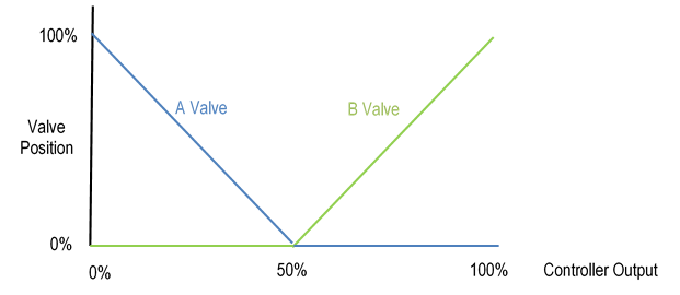
Figure 1 shows why this strategy is called V-shaped. As the controller output moves from 0% to 50%, the A valve (blue line) moves from 100% to 0% while the B valve (green line) is closed. From 50% to 100% on the controller output, the B valve moves from 0% to 100% while the A valve is closed. In this example, the breakpoint between valve openings is 50%. However, the breakpoint may need to be moved if the valves respond differently.
Inverted V Split-Range
The inverted V split-range is used where one valve throttles while the other is wide open. The main example of this approach is flow-splitting between two parallel lines.
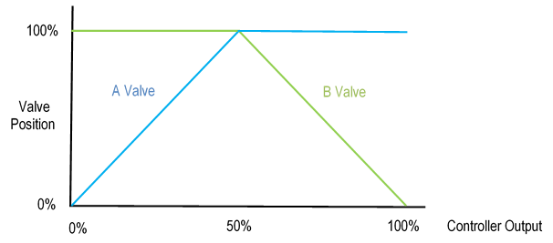
Figure 2 shows why this strategy is called inverted V. As the controller output moves from 0% to 50%, the A valve moves from 0% to 100% while the B valve is wide open. From 50% to 100% on the controller output, the B valve moves from 100% to 0% while the A valve is wide open. As in the previous example, the breakpoint between valve openings is 50%. However, the breakpoint may need to be moved if the valves respond differently.
Staged Valves Split-Range
Staged valve split-range is used where one valve goes from closed to open before the other valve opens. The main example of this approach is precision flow control where two smaller valves are used in place of one larger valve.
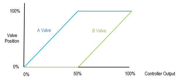
Figure 3 shows this strategy. As the controller output moves from 0% to 50%, the A valve moves from 0% to 100% while the B valve is closed. From 50% to 100% on the controller output, the B valve moves from 0% to 100% while the A valve is wide open. Once again, the breakpoint between valve openings is 50%. However, the breakpoint may need to be moved if the valves respond differently.
Split-Range Overlap
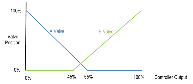
The split-range may be overlapped as shown in Figure 4. As the controller output moves from 0% to 55%, the A valve moves from 100% to 0%. From 45% to 100% on the controller output, the B valve moves from 0% to 100%. Both valves are open between 45% and 55% controller output.
Overlap is useful when the control valves do not actually pass any flow at low valve positions. The B valve gets a head start by opening at 45% rather than 50%.
Split-Range Gap
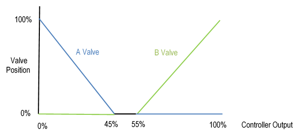
The split-range may have a gap as shown in Figure 5. As the controller output moves from 0% to 45%, the A valve moves from 100% to 0%. From 55% to 100% on the controller output, the B valve moves from 0% to 100%. Both valves are closed between 45% and 55% controller output.
Gap is useful when it is important that only one valve be open at a time. However, this arrangement imposes a dead zone in the controller response.
CONTROL SCHEME
Pressure Vessel Makeup / Dump Control
Figure 6 illustrates the control scheme for a pressure vessel that utilizes natural gas to increase pressure and a dump valve to the flare to reduce pressure. The V-shaped split-range scheme (see Figure 1) is used to prevent simultaneously making up with natural gas and dumping the gas to flare.
The vessel pressure controller (PC) sends its output to the split-range controller (S/R) which adjusts the two valves, A for makeup and B for flaring. Each valve is adjusted by a hand controller (HC) which sends the split-range calculation result to the valve when the HC is in automatic. The HC can be put into manual to adjust the valve independent of the split-range whenever necessary (e.g., valve stroking after maintenance).
In the Foxboro I/A control system, the BIAS block is used for the HC. It has the useful feature of ramping the valve to the split-range position after the HC is put into automatic. When the ramp is tuned properly, the transfer to automatic is nearly bumpless.

Split-Range Output Calculations
The split-range controller calculates the output to the two valves using the standard linear equation:
Output = Slope * Input + Intercept (1)
The slope and intercept are calculated using two points on the line: (Input1, Output1) and (Input2, Output2):
Slope = (Output2 – Output1) / (Input2 – Input1) (2)
Intercept = Output1 – (Slope * Input1) (3)
Substituting and rearranging equation 1 yields the following equation:
Output = Slope * (Input – Input1) + Output1 (4)
Split-Range Output Calculation Example
In the case of the V-shaped split-range shown in Figure 1, the slope for the A valve is calculated as follows:
Slope = (Output2 – Output1) / (Input2 – Input1) = (0 – 100) / (50 – 0) = -2.0 (5)
The resulting equation for the A valve is:
Output = -2.0 * Input + 100 (6)
Following the same procedure for the B valve yields this equation:
Output = 2.0 * Input – 100 (7)
External Reset Feedback
External reset feedback is used to prevent a primary controller from winding-up when its secondary controller becomes limited, either by hitting an output limit or by being overridden. The feedback signal must be back-calculated based on the forward calculation of the control blocks being used.
The feedback calculation, also called the back calculation, is obtained by rearranging Equation 4, where FBK replaces Input in the equation:
FBK = (Output – Output1) / Slope + Input1 (8)
For the A valve, the feedback equation is:
FBK = (Output – 100) / -2.0 (9)
And for the B valve, the feedback equation is:
FBK = (Output + 100) / 2.0 (10)
The problem with a split-range application is that each secondary has a different FBK calculation, but the primary can take only one FBK input. The following examples illustrate this point.
External Reset Feedback Example 1
In the example in Figure 7 below, the feedback signal for the A valve is calculated using equation 9 as follows:
FBK = (80 – 100) / (-2.0) = 10 (which is the PC output) (11)
The feedback signal for the B valve is calculated using equation 10 as follows:
FBK = (0 + 100) / (2.0) = 50 (which is not the PC output) (12)
The feedback signal to choose is the A valve because it is between its high and low limits. The B valve is at its low limit, which is the breakpoint, so its feedback is not valid.

External Reset Feedback Example 2
In the example in Figure 8 below, the feedback signal for the A valve is calculated using equation 9 as follows:
FBK = (0 – 100) / (-2.0) = 50 (which is not the PC output) (13)
The feedback signal for the B valve is calculated using equation 10 as follows:
FBK = 20 + 100 / (2.0) = 60 (which is the PC output) (14)
In this case, the feedback signal to choose is the B valve because it is between its high and low limits. The A valve is at its low limit, which is the breakpoint, so its feedback is not valid.

Feedback Logic
The previous discussion indicates that the following logic should be used to determine the feedback signal to the primary controller:
- When the A valve is not at its breakpoint limit, then its calculated feedback signal should be the feedback to the primary. The B valve feedback calculation should be ignored.
- When the A valve is at its breakpoint limit, then its calculated feedback signal should be ignored. The B valve feedback calculation should be the feedback to the primary.
Primary Controller Initialization
When all HCs are in manual and one of them is put into automatic, the primary controller’s output should initialize to that HC’s feedback calculation. For example, assume that both HCs in Figure 8 are in manual. If the HC for the A valve is put into automatic, then the PC output should initialize to the A valve feedback signal (50%) because the A valve is the only one in automatic.
When the second HC is put into automatic, then the PC output should re-initialize to the feedback signal determined by the logic described above. For example using Figure 8 again, if the HC for the A valve is in automatic and the HC for the B valve is put into automatic, then the B valve feedback signal (60%) should be used because the A valve is at its breakpoint limit.
When either HC mode is changed, including automatic to manual, the PC output should be re-initialized. This action ensures that the PC output is always lined up with the active valve.
FOXBORO I/A IMPLEMENTATION
Application Components
A typical split-range application contains the following blocks:
- Primary controller (PC0010 in Figure 9).
- CALCA block containing split-range logic (PY0010 in Figure 9).
- BIAS controllers (HC0001/2 in Figure 9).
- ROUT block for each valve (PV0001/2 in Figure 9).

Primary Controller Block PC0010
The primary controller PC0010 should have the following connections:
INITI = :PY0010.BO01
BCALCI = :PY0010.RO03
FBK = :PY0010.RO03
Its output should be connected to PY0010.RI03.
Split-Range Block PY0010
PY0010 is a CALCA block that performs the Split-Range calculations (equation 4) for each valve. It also performs the feedback calculations (equation 8), the logic for selecting the proper feedback to the primary controller PC0010, and the initialization logic.
RI01 = :PV0001.BCALCO (Valve A Position)
RI02 = :PV0002.BCALCO (Valve B Position)
RI03 = :PC0010.OUT
BI01 = :PV0001.INITO
BI02 = :PV0002.INITO
BI03 = :HC0001.LOLIND (Valve A at low output limit)
BI04 = :HC0001.MA
BI05 = :HC0002.MA
Also, the block mode should be locked to automatic:
MA = : PY00010.MA.1
The block parameters must be set as follows:
TIMINI = 3
M10 = 5.0 (OSP time for initialization)
M11 = primary controller minimum output pertaining to valve A (0.0)
M12 = primary controller maximum output pertaining to valve A (breakpoint)
M13 = valve A output at primary controller output in M11
M14 = valve A output at primary controller output in M12
M15 = primary controller minimum output pertaining to valve B (breakpoint)
M16 = primary controller maximum output pertaining to valve B (100.0)
M17 = valve B output at primary controller output in M15
M18 = valve B output at primary controller output in M16
V-Shaped Split-Range Configuration
The V-shaped split-range shown in Figure 1 is configured as follows in block PY0010:
M11 = 0.0
M12 = 50.0
M13 = 100.0
M14 = 0.0
M15 = 50.0
M16 = 100.0
M17 = 0.0
M18 = 100.0
Inverted V Split-Range Configuration
The inverted V split-range shown in Figure 2 is configured as follows in block PY0010:
M11 = 0.0
M12 = 50.0
M13 = 0.0
M14 = 100.0
M15 = 50.0
M16 = 100.0
M17 = 100.0
M18 = 0.0
Staged Valve Split-Range Configuration
The staged valve split-range shown in Figure 3 is configured as follows in block PY0010:
M11 = 0.0
M12 = 50.0
M13 = 0.0
M14 = 100.0
M15 = 50.0
M16 = 100.0
M17 = 0.0
M18 = 100.0
Split-Range Overlap Configuration
The split-range overlap shown in Figure 4 is configured as follows in block PY0010:
M11 = 0.0
M12 = 55.0
M13 = 100.0
M14 = 0.0
M15 = 45.0
M16 = 100.0
M17 = 0.0
M18 = 100.0
Split-Range Gap Configuration
The split-range gap shown in Figure 5 is configured as follows in block PY0010:
M11 = 0.0
M12 = 45.0
M13 = 100.0
M14 = 0.0
M15 = 55.0
M16 = 100.0
M17 = 0.0
M18 = 100.0
Split-Range Block Steps
STEP01 = SUB M14 M13 ;SEC1 FWD CALC
STEP02 = SUB M12 M11
STEP03 = DIV
STEP04 = OUT M01 ;SEC1 SLOPE
STEP05 = SUB RI03 M11
STEP06 = MUL
STEP07 = ADD M13
STEP08 = OUT RO01 ;SEC1 MEAS
STEP09 = SUB M18 M17 ;SEC2 FWD CALC
STEP10 = SUB M16 M15
STEP11 = DIV
STEP12 = OUT M02 ;SEC2 SLOPE
STEP13 = SUB RI03 M15
STEP14 = MUL
STEP15 = ADD M17
STEP16 = OUT RO02 ;SEC2 MEAS
STEP17 = OR BI01 ~BI04 ;SEC1 INITO OR MAN
STEP18 = OUT BO03 ;SEC1 NOT CASC
STEP19 = OR BI02 ~BI05 ;SEC2 INITO OR MAN
STEP20 = OUT BO04 ;SEC2 NOT CASC
STEP21 = AND BO03 BO04 ;PRIMARY INIT
STEP22 = OUT BO01
STEP23 = OR BO03 BI03 ;SEC1 INIT OR LIMITED
STEP24 = BIT 35
STEP25 = SUB M14 M13
STEP26 = BIP 29
STEP27 = SUB M14 RI01
STEP28 = GTO 31
STEP29 = SUB RI01 M14
STEP30 = BIP 35
STEP31 = SUB RI01 M13 ;SEC1 BCALC
STEP32 = DIV M01
STEP33 = ADD M11
STEP34 = GTO 38
STEP35 = SUB RI02 M17 ;SEC2 BCALC
STEP36 = DIV M02
STEP37 = ADD M15
STEP38 = OUT RO03 ;PRIM BCALC
STEP39 = IN BO03 ;SEC1 NOT CASCADE
STEP40 = OSP M10
STEP41 = IN ~BO03 ;SEC1 IN CASCADE
STEP42 = OSP M10
STEP43 = IN BO04 ;SEC2 NOT CASCADE
STEP44 = OSP M10
STEP45 = IN ~BO04 ;SEC2 IN CASCADE
STEP46 = OSP M10
STEP47 = OR 4
STEP48 = OUT BO02 ;INIT TO BIAS BLOCKS
STEP49 = OR BO01
STEP50 = OUT BO01 ;PRIMARY INITI
Split-Range Block Logic Details
Steps 1-8: Calculate the output to valve A (secondary 1) using equations 2 and 4, and store the result to RO01.
Steps 9-16: Calculate the output to valve B (secondary 2) using equations 2 and 4, and store the result to RO02.
Steps 17-18: Determine whether the A valve’s ROUT or BIAS block is in manual and store the result to BO03. Note: BO03 is on if the cascade is broken.
Steps 19-20: Determine whether the B valve’s ROUT or BIAS block is in manual and store the result to BO04. Note: BO04 is on if the cascade is broken.
Steps 21-22: If both BO03 and BO04 are on, then initialize the primary controller via BO01.
Steps 23-24: If valve A cascade is broken (BO03) or at its breakpoint limit (BI03), then go to step 35 to use valve B for the back calculation.
Steps 25-30: Determine whether valve A is within its part of the split-range. If not, go to step 35 to use valve B for the back calculation.
Steps 31-34: Back-calculate the feedback signal for valve A using equation 8, and go to step 38 to store the result in RO03.
Steps 35-38: Back-calculate the feedback signal for valve B using equation 8, and store the result in RO03.
Steps 39-48: Determine whether a change in mode has occurred with either of the valves and store a one-shot pulse to BO02. BO02 is connected to the INITI parameter of both BIAS blocks.
Steps 49-50: OR BO02 with BO01 and store the result to BO01, which is connected to the primary controller’s INITI parameter.
Bias Controller Block HC0001
The bias controller HC0001 manipulates control valve PV0001 via an ROUT block. The other bias controller HC0002 is similar. HC0001 has the following connections:
MEAS = :PY0010.RO01
INITI = :PY0001.BO02
BCALCI = :PV0001.BCALCO
The block parameters must be set as follows:
HSCI1 = 100 (Same as range of PC0010 output)
LSCI1 = 0
KMEAS = 1.0
REMSW = :HC0001.REMSW.1 (Lock in remote)
RBIAS = :HC0001.RBIAS.0.0 (Lock to zero)
BTRKOP = 0
BTIME = First-order lag (minutes) used in ramping the valve to the split-range position.
Block Execution Order
The block execution order is important to the proper functioning of the application:
- Primary controller (PC0010)
- Split-Range controller (PY0010)
- Bias controllers (HC0001 and HC0002)
- ROUT blocks for control valves (PV0001 and PV0002)
