
Introduction
In a previously released functional specification, Strategic Automation Services (SAS) described centrifugal compressor process controls that can be executed in the Foxboro DCS using standard I/A blocks. However, that functional specification did not include details of how to implement the controls. This document provides those details. Most of the discussion in the previous functional specification is repeated here to present a more complete picture of the controls.
Anti-surge control keeps the flow through the compressor above the surge point by adjusting a blow off vent (for air blowers) or recycle control valve. The surge point is obtained from the compressor performance curves or from compressor surge testing.
Summary of Features
The SAS compressor anti-surge controls include the following features:
- Minimum control margin to define the control line.
- Variable control margin which increases the control margin when operating far away from the surge control line.
- Adaptive controller tuning to speed up response as the compressor approaches the control line.
- Asymmetrical control action to prevent the anti-surge valve from closing too fast.
- Surge line violation detection and automatic control margin increase.
These features are discussed in more detail in the following sections of this document.
Compressor Performance Curves
A typical performance curve for a variable speed compressor is shown in Figure 1a, and the performance curve for a fixed-speed compressor is shown in Figure 1b.
The curves show the relationship between the head generated by the compressor and the resulting flow. The relationship is inverse, meaning that as the head increases, the flow decreases, and as the head decreases, the flow increases.
At high head, the curve terminates at the surge point. If the flow is reduced below this point, the compressor suffers rapid flow reversal, which is called surge. Surge can cause extensive compressor damage if it is not quickly counteracted.
The surge points form a surge line. This line is used to determine the minimum flow through the compressor. The current head is calculated from the suction and discharge pressures, and the surge line is used to look up the surge flow.


Performance Cure Axes
The variables head and suction flow are typically used as axes for performance curves. However, the surge curve plotted on these axes is not independent of gas conditions (i.e., suction pressure, suction temperature, molecular weight). Therefore, the following parameters are used instead:
- Pressure ratio (Rc) for the y-axis.
- Suction flow orifice differential pressure corrected for pressure (hc) for the x-axis.
Surge curves plotted on these axes are relatively unaffected by changes in gas conditions. The equations for these parameters are as follows:
Rc = Pd / Ps (1)
hc = hsrg * Psr / Ps (2)
where:
Pd = discharge pressure (absolute)
Ps = suction pressure (absolute)
hsrg = suction orifice differential pressure at surge
Psr = suction reference pressure at which surge curve data was obtained
Anti-Surge Flow Setpoint Calculation – Suction Orifice
A characterizer block is used to perform a table lookup of Rc vs. hc. The suction surge flow hsrg can then be calculated by rearranging equation 2:
hsrg = hc * Ps / Psr (3)
The term hsrg is converted to suction flow as follows:
Fsrg = Fmax * SQRT (hsrg / hmax) (4)
where:
Fsrg = surge point in terms of suction conditions
Fmax = orifice flow range
hmax = maximum orifice diff pressure (e.g., 100 if hsrg is in percent of range)
Anti-Surge Flow Setpoint Calculation – Discharge Orifice
The term hsrg in equation 3 is at suction conditions. If the flow meter is in the discharge line, then hsrg must be adjusted to discharge conditions and the surge flow Fsrg calculated as follows:
ho = hsrg * (ρor / ρo) * (ρs / ρsr) (5)
Fsrg = Fmax * SQRT (ho / hmax) (6)
where:
ho = orifice differential pressure at discharge conditions
ρo = flowing density at actual orifice conditions
ρor = flowing density at reference orifice conditions
ρs = flowing density at actual suction conditions
ρsr = flowing density at reference suction conditions
Fmax = orifice flow range
For ideal gases, flowing density can be calculated as follows:
ρ = P * M / (R * T * Z) (7)
where:
P = absolute pressure
M = molecular weight
R = ideal gas constant
T = absolute temperature
Z = compressibility
Minimum Control Margin
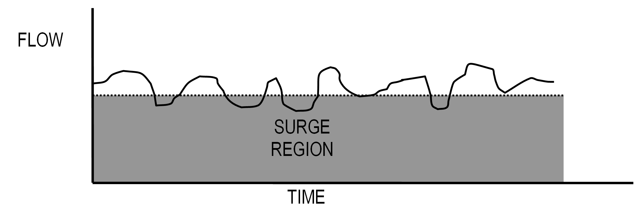
The anti-surge controller must always maintain the flow through the compressor above the surge point. However, if the controller attempts to control at the surge point, then minor fluctuations could cause the compressor to go into surge before the controller could take control action, as shown in Figure 2.
Therefore, a minimum control margin is added to the surge point. The margin ensures that the flow will be slightly above the surge point even during minor fluctuations, as shown in Figure 3.

Control Point Equation
The equation for calculating the control point is as follows:
Fctl = Fsrg * (1 + Km / 100) (8)
where:
Fctl = control point
Fsrg = surge flow
Km = minimum control margin in %.
Variable Control Margin
A variable control margin is added to the control point before it is stored to the setpoint of the anti-surge flow controller. The objective of the variable control margin is to provide additional protection against a sudden loss of flow. The variable margin provides the anti-surge controller with more time to open the recycle or blowoff valve before surge is reached.
Variable Control Margin Examples
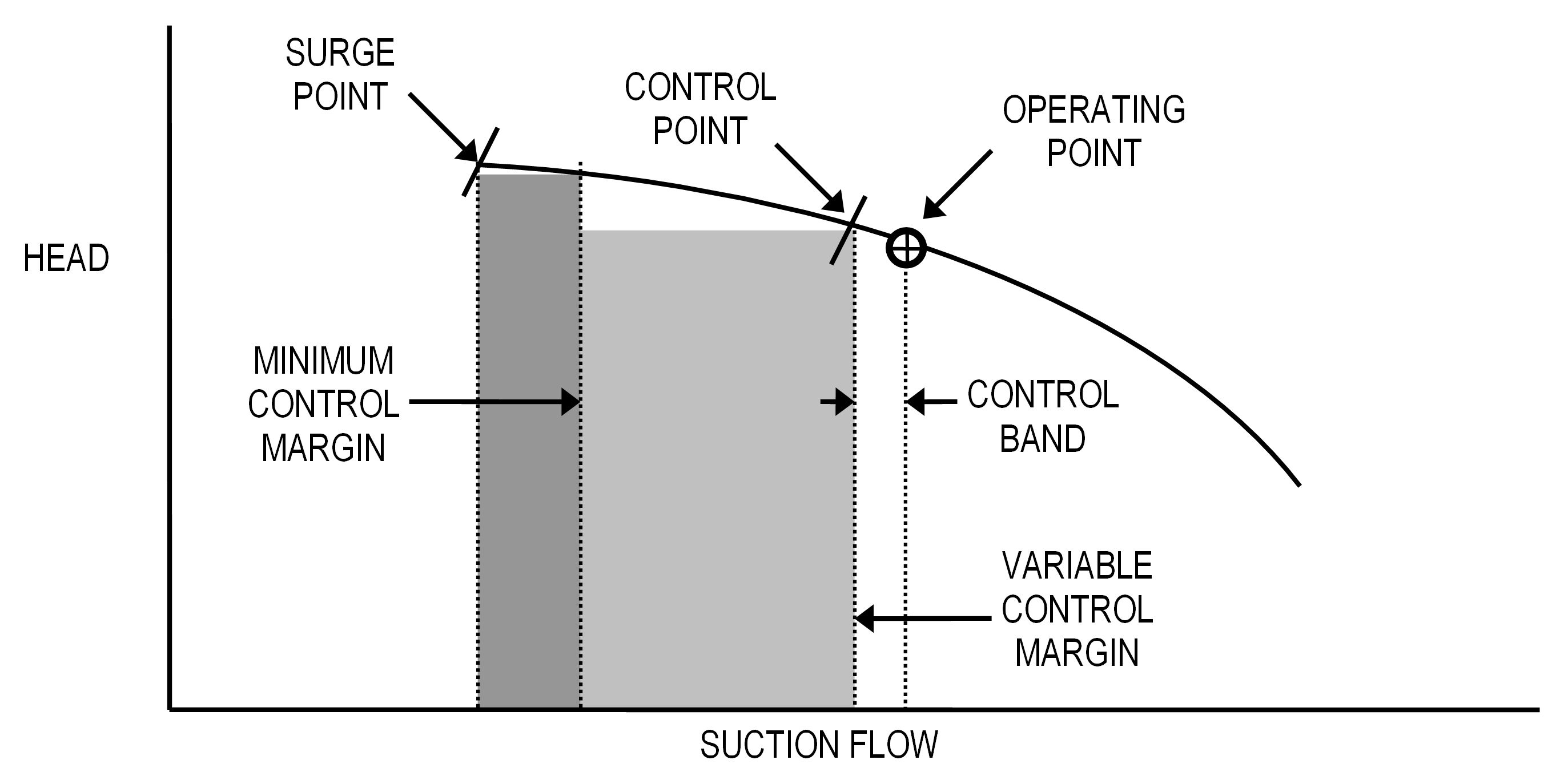
The variable control margin concept can be illustrated using a performance curve like Figure 1b. Figure 4 shows the compressor operating well above the minimum control margin. The anti-surge flow controller setpoint (control point) is set within an engineer-entered control band below the current operating point.
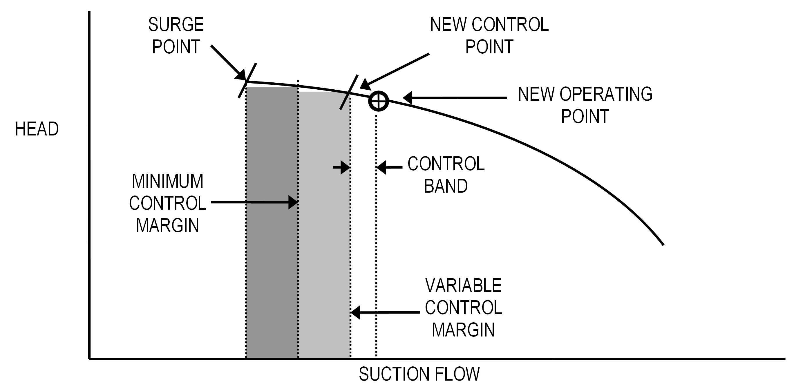
If the flow drops off and the anti-surge controller opens the recycle or blowoff valve, the variable control margin is ramped down at an engineer-entered rate until either the valve is closed, or the minimum control margin is reached. Figure 5 shows the variable margin re-established at a lower flow rate.
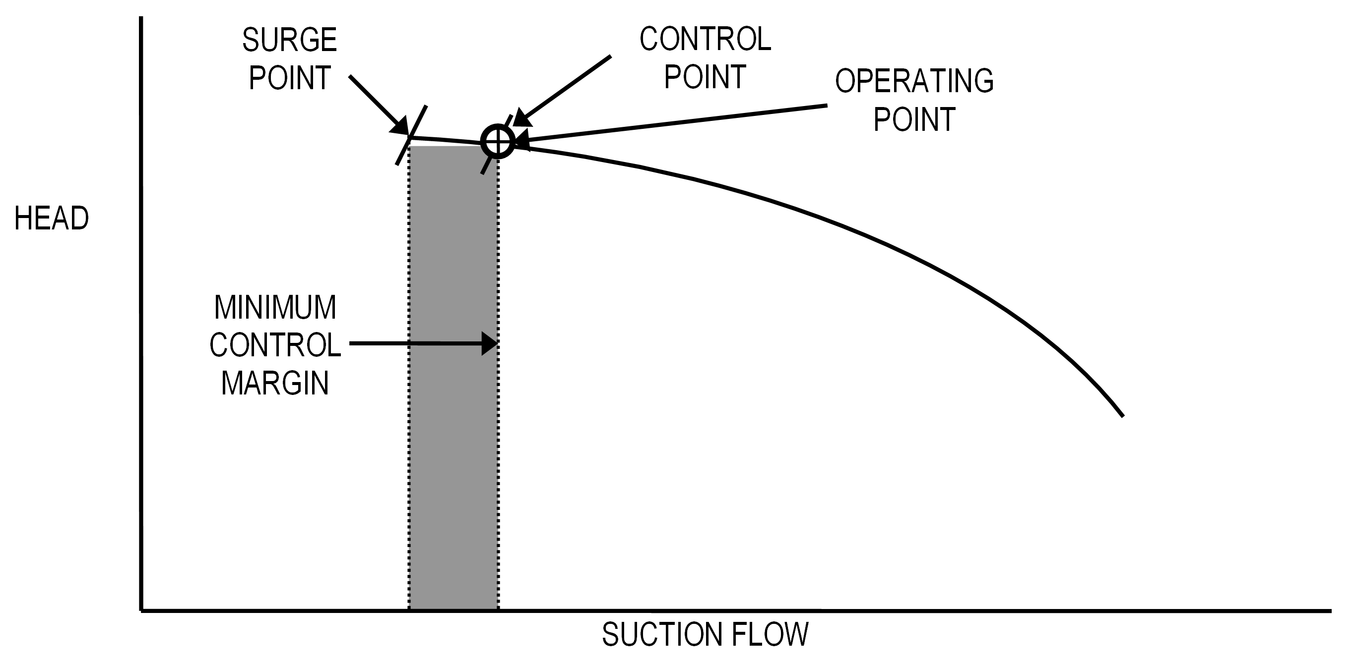
Figure 6 shows the compressor operating at the minimum margin. In this case, there is no variable margin because the operation is too close to the surge point.
Variable Margin Equations
The equations for variable control margin are as follows:
Fspt = Ffilt – Fband (9)
where:
Fspt = anti-surge flow controller RSP
Ffilt = anti-surge flow controller MEAS (filtered)
Fband = anti-surge flow control band
The anti-surge flow controller MEAS is filtered (Ffilt) to prevent short-term fluctuations from affecting the variable control margin calculation. The filtering algorithm is implemented as follows:
Ffilt = [Fold * Kfilt] + [Fmeas * (1 – Kfilt)] (10)
where:
Fmeas = anti-surge flow controller MEAS input
Fold = previous value of Ffilt
Kfilt = filter constant (0=no filter; 1=total filter)
Anti-Surge Flow Control
The previous sections describe how the setpoint is arrived at for the anti-surge controller. This controller is basically a flow controller that adjusts the anti-surge valve at a frequency of at least 500 ms, and in some applications 100 ms, to control the flow measurement at or above the setpoint. The controller includes several advanced control techniques, which are discussed next.
Adaptive Controller Tuning
The anti-surge flow controller tuning is automatically adjusted depending upon whether the flow is above or below the setpoint. Normal tuning is used when the flow is above setpoint. When the flow is below setpoint, the controller tuning is set faster to quickly return the flow to setpoint. How fast the tuning is set depends upon how far below setpoint the flow has fallen.
Adaptive Tuning Equations
The equations for adaptive tuning are as follows:
Padapt = Pnorm / Kadapt (11)
Iadapt = Inorm / Kadapt (12)
Kadapt = 2 ** {100 * [1 – (Fmeas / Fspt)] / Kdev} (13)
where:
Padapt = adapted PBAND used in anti-surge controller
Pnorm = PBAND setting for normal operation (above control point)
Iadapt = adapted INT used in anti-surge flow controller
Inorm = INT setting for normal operation (above control point)
Kadapt = adaptive tuning factor (limited to a minimum of 1.0)
Fmeas = anti-surge controller MEAS
Fspt = anti-surge controller SPT
Kdev = anti-surge controller negative deviation at which tuning constants are halved (% of SPT)
Asymmetrical Control Action
The adaptive tuning technique previously discussed can result in extremely rapid opening and closing of the recycle or blowoff valve. This is especially likely as the flow approaches surge because the flow input will become noisier.
To prevent this potential control instability, the SAS compressor anti-surge controls include asymmetrical control action. This feature allows the recycle or blowoff valve to open quickly to avoid surge, but close gradually to prevent upsetting other control functions.
Surge Line Violation
As the compressor operation approaches the surge line, the flow through the compressor can become erratic. If the flow reaches the surge line, then the control margin is automatically increased to push the control line further away from the surge line. An alarm can also be issued, if desired. The margin can increase only up to the maximum margin specified by the engineer.
The control margin can be set back to the original minimum control margin either automatically or manually. The automatic reset is based on elapsed time since the last event. The reset time is set by the engineer. The manual reset is via a button on the anti-surge control graphic display.
Frequent surge line violations are a sign that the minimum control margin is too close to the actual surge point. Therefore, the minimum control margin should be gradually increased until the violations become less frequent.
Input Checking
The SAS compressor control logic checks each input and takes appropriate action in the event of a bad value. The following inputs are checked:
- Anti-surge flow input
When a bad input is detected, the anti-surge controller input is set slightly above zero thus causing the anti-surge valve to go wide open.
- Pressures and Temperatures
The suction pressure, suction temperature, discharge pressure and discharge temperature are limited to minimum and maximum values. When a bad input is detected, these inputs are set to the safest possible setpoint for the anti-surge controller.
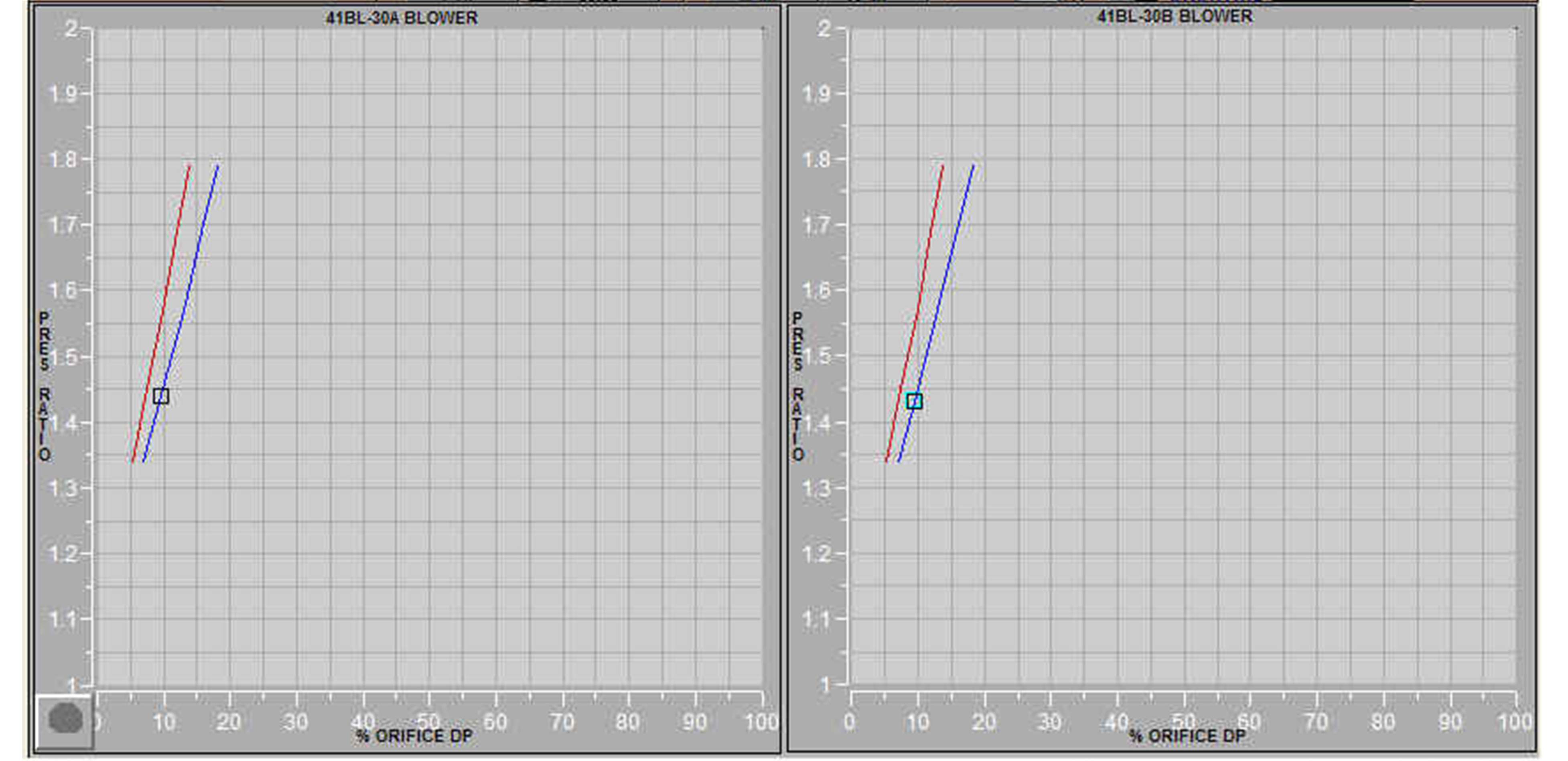
X-Y Plot
A plot of pressure ratio versus flow (% orifice dP) is typically included for each compressor. It can be called up from the process display by clicking the mouse on a button labeled XY PLOT. For dual parallel compressors, both plots can be configured to appear side-by-side, as shown in Figure 7.
The surge line appears in red, and the minimum control line appears in blue. The current operating point is shown as a black square. The operating point is continuously updated to reflect the current conditions. Previous positions of the operating point appear as light green squares.
DCS Implementation
The SAS compressor anti-surge controls are implemented via standard Foxboro I/A blocks. Each compressor has its own compound containing a similar set of blocks. An FCP270 can host the controls for at least seven compressors, but multiple compressors are typically distributed among several control processors. Therefore, the number of compressors in a single CP is seldom more than two.
DCS IMPLEMENTATION – INPUT BLOCKS
Anti-Surge Input Blocks
Figure 8 shows the block schematic for the input blocks in a typical compressor anti-surge control application (should be executed in this order):
- CALCA block for checking the suction pressure input (PS_CHECK).
- CALCA block for checking the suction temperature input (TS_CHECK).
- CALCA block for checking the discharge pressure input (PD_CHECK).
- CALCA block for checking the discharge temperature input (TD_CHECK).
- CALCA block for calculating pressure ratio (P_RATIO).
- CALCA block for calculating the suction flow compensation factor (FLOW_SUCT).
- CALCA block for calculating the discharge flow compensation factor (FLOW_DSCH).
Note: Blocks TD_CHECK and FLOW_DSCH are not required if the anti-surge flow orifice is in the suction.

Suction Pressure Input Check Block PS_CHECK
PS_CHECK is a CALCA block that checks the suction pressure input for bad input and for violation of maximum and minimum limits. If necessary, the block can also convert the input to absolute units (e.g., PSIG to PSIA). The following connections are required:
RI01 = Suction pressure
BI01 = Suction pressure bad input (lock to zero if bad status can be obtained from the RI01 input via the RDB command)
BI02 = Hold signal from another block (lock to zero if no other hold signal)
MA = :PS_CHECK.MA.1 (lock to auto)
The block parameters must be set as follows:
PERIOD = Fastest execution frequency available
RI03 = Suction pressure minimum limit (same units as RI01)
RI04 = Suction pressure maximum limit (same units as RI01)
TIMINI = 3
M01 = Hold signal pulse time (sec)
M02 = Absolute conversion (0.0 if suction pressure is PSIA or 14.7 if PSIG)
M03 = Bad input signal delay on time (sec)
M04 = Bad input signal delay off time (sec)
The block generates the following outputs:
RO01 = Suction pressure in absolute units (RO04 substituted if input is bad)
RO02 = Suction pressure in absolute units (RO03 substituted if input is bad)
RO03 = Low limit (RI03) converted to absolute units
RO04 = High limit (RI04) converted to absolute units
BO01 = Anti-surge controller hold signal
BO02 = Flag denoting that input has been limited to the low limit
BO03 = Flag denoting that input has been limited to the high limit
BO04 = Bad input flag
BO05 = Bad input flag (delayed)
M11 = Suction pressure (RI01) converted to absolute units
Suction Pressure Input Check Block Steps
STEP01 = ADD RI03 M02 ;MIN INP + ABS
STEP02 = OUT RO03 ;ABS MIN INPUT
STEP03 = ADD RI04 M02 ;MAX INP + ABS
STEP04 = OUT RO04 ;ABS MAX INPUT
STEP05 = CLR BO02 ;MIN LIMIT FLAG
STEP06 = CLR BO03 ;MAX LIMIT FLAG
STEP07 = RBD RI01 ;BAD INPUT
STEP08 = OR BI01 ;BAD INPUT
STEP09 = OUT BO04 ;BAD FLAG
STEP10 = DON M03 ;FILTER OUT BLIPS
STEP11 = DOFF M04 ;DELAY GOING GOOD
STEP12 = OUT BO05 ;BAD FLAG DELAYED
STEP13 = IN BO04
STEP14 = BIF 21
STEP15 = IN BO05
STEP16 = BIF 36 ;FILTER OUT BLIPS
STEP17 = IN RO04 ;ABS MAX INPUT
STEP18 = OUT RO01 ;ABS INP (HI IF BAD)
STEP19 = IN RO03 ;ABS MIN INPUT
STEP20 = GTO 35
STEP21 = ADD RI01 M02 ;CONV TO ABS
STEP22 = OUT M11
STEP23 = SUB M11 RO04 ;CK MAX LIM
STEP24 = BIN 28
STEP25 = SET BO03 ;MAX LIM FLAG
STEP26 = IN RO04
STEP27 = GTO 34
STEP28 = SUB M11 RO03 ;CK MIN LIM
STEP29 = BIP 33
STEP30 = SET BO02 ;MIN LIM FLAG
STEP31 = IN RO03
STEP32 = GTO 34
STEP33 = IN M11
STEP34 = OUT RO01 ;ABS INP (HI IF BAD)
STEP35 = OUT RO02 ;ABS INP (LO IF BAD)
STEP36 = CST
STEP37 = IN BO05 ;INP BECOMING BAD
STEP38 = OSP M01
STEP39 = IN ~BO05 ;INP BECOMING GOOD
STEP40 = OSP M01
STEP41 = IN BI02 ;HOLD SIG FM OTHER BLK
STEP42 = OR 3
STEP43 = OUT BO01 ;ASC HOLD SIGNAL
STEP44 = END
Suction Pressure Input Check Block Logic Details
Steps 1-4: Convert limits to absolute units and store minimum limit to RO03 and maximum limit to RO04.
Steps 5-6: Clear limit violation flags BO02 and BO03. These flags will be set in steps 25 and 30 if the limits are violated.
Steps 7-9: Determine if the input (RI01 or BI01) is bad and store the result to BO04.
Steps 10-12: Perform a delay on and a delay off and store the result to BO05. The purpose is to filter out blips in the bad status that would cause a needless bump in the controls.
Steps 13-14: If the bad flag BO04 is off, then go to step 21.
Steps 15-16: If the delayed bad flag BO05 is off, then go to step 36.
Steps 17-20: The delayed bad flag BO05 is on, so store the maximum limit (RO04) to RO01 and go to step 35 to store the minimum limit (RO03) to RO01.
Steps 21-22: Convert the input to absolute units by adding M02 and store the result to M11.
Steps 23-27: If the input (M11) is above the maximum limit (RO04), then set the limit violation flag BO03 and go to step 34 to store the maximum limit to both RO01 and RO02.
Steps 28-32: If the input (M11) is below the minimum limit (RO03), then set the limit violation flag BO02 and go to step 34 to store the minimum limit to both RO01 and RO02.
Steps 33-35: The input (M11) is within the limits (RO03), so store it to both RO01 and RO02.
Steps 37-43: Generate an on pulse when the delayed bad flag (BO05) has just become bad or when it has just become good. OR the result with BI02 and store to BO01.
Suction Temperature Input Check Block TS_CHECK
TS_CHECK is a CALCA block that checks the suction temperature input for bad input and for violation of maximum and minimum limits. The block also converts the input to absolute units (e.g., DEGF to DEGR). The following connections are required:
RI01 = Suction temperature
BI01 = Suction temperature bad input (lock to zero if bad status can be obtained from the RI01 input via the RDB command)
BI02 = :PS_CHECK.BO01 (hold signal)
MA = :TS_CHECK.MA.1 (lock to auto)
The block parameters must be set as follows:
PERIOD = Fastest execution frequency available
RI03 = Suction temperature minimum limit (same units as RI01)
RI04 = Suction temperature maximum limit (same units as RI01)
TIMINI = 3
M01 = Hold signal pulse time (sec)
M02 = Absolute conversion (460.0)
M03 = Bad input signal delay on time (sec)
M04 = Bad input signal delay off time (sec)
The block generates the following outputs:
RO01 = Suction temperature in absolute units (RO04 substituted if input is bad)
RO02 = Suction temperature in absolute units (RO03 substituted if input is bad)
RO03 = Low limit (RI03) converted to absolute units
RO04 = High limit (RI04) converted to absolute units
BO01 = Anti-surge controller hold signal
BO02 = Flag denoting that input has been limited to the low limit
BO03 = Flag denoting that input has been limited to the high limit
BO04 = Bad input flag
BO05 = Bad input flag (delayed)
M11 = Suction temperature (RI01) converted to absolute units
Suction Temperature Input Check Block Steps
The steps for block TS_CHECK are identical to those for PS_CHECK.
Discharge Pressure Input Check Block PD_CHECK
PD_CHECK is a CALCA block that checks the discharge pressure input for bad input and for violation of maximum and minimum limits. If necessary, the block can also convert the input to absolute units (e.g., PSIG to PSIA). The following connections are required:
RI01 = Discharge pressure
BI01 = Discharge pressure bad input (lock to zero if bad status can be obtained from the RI01 input via the RDB command)
BI02 = :TS_CHECK.BO01 (hold signal)
MA = :PD_CHECK.MA.1 (lock to auto)
The block parameters must be set as follows:
PERIOD = Fastest execution frequency available
RI03 = Discharge pressure minimum limit (same units as RI01)
RI04 = Discharge pressure maximum limit (same units as RI01)
TIMINI = 3
M01 = Hold signal pulse time (sec)
M02 = Absolute conversion (0.0 if discharge pressure is PSIA or 14.7 if PSIG)
M03 = Bad input signal delay on time (sec)
M04 = Bad input signal delay off time (sec)
The block generates the following outputs:
RO01 = Discharge pressure in absolute units (RO04 substituted if input is bad)
RO02 = Discharge pressure in absolute units (RO03 substituted if input is bad)
RO03 = Low limit (RI03) converted to absolute units
RO04 = High limit (RI04) converted to absolute units
BO01 = Anti-surge controller hold signal
BO02 = Flag denoting that input has been limited to the low limit
BO03 = Flag denoting that input has been limited to the high limit
BO04 = Bad input flag
BO05 = Bad input flag (delayed)
M11 = Discharge pressure (RI01) converted to absolute units
Discharge Pressure Input Check Block Steps
The steps for block PD_CHECK are identical to those for PS_CHECK.
Discharge Temperature Input Check Block TD_CHECK
TD_CHECK is a CALCA block that checks the suction temperature input for bad input and for violation of maximum and minimum limits. The block also converts the input to absolute units (e.g., DEGF to DEGR). The following connections are required:
RI01 = Discharge temperature
BI01 = Discharge temperature bad input (lock to zero if bad status can be obtained from the RI01 input via the RDB command)
BI02 = :PD_CHECK.BO01 (hold signal)
MA = :TD_CHECK.MA.1 (lock to auto)
The block parameters must be set as follows:
PERIOD = Fastest execution frequency available
RI03 = Discharge temperature minimum limit (same units as RI01)
RI04 = Discharge temperature maximum limit (same units as RI01)
TIMINI = 3
M01 = Hold signal pulse time (sec)
M02 = Absolute conversion (460.0)
M03 = Bad input signal delay on time (sec)
M04 = Bad input signal delay off time (sec)
The block generates the following outputs:
RO01 = Discharge temperature in absolute units (RO04 substituted if input is bad)
RO02 = Discharge temperature in absolute units (RO03 substituted if input is bad)
RO03 = Low limit (RI03) converted to absolute units
RO04 = High limit (RI04) converted to absolute units
BO01 = Anti-surge controller hold signal
BO02 = Flag denoting that input has been limited to the low limit
BO03 = Flag denoting that input has been limited to the high limit
BO04 = Bad input flag
BO05 = Bad input flag (delayed)
M11 = Discharge temperature (RI01) converted to absolute units
Discharge Temperature Input Check Block Steps
The steps for block TD_CHECK are identical to those for PS_CHECK.
Suction Flow Calculation Block FLOW_SUCT
FLOW_SUCT is a CALCA block that is used to compensate flow for changes in pressure and temperature. It is also used in the anti-surge application to calculate the gas density at suction conditions (ρs) using equation 7. The block also calculates the gas density at reference conditions (ρsr) and the flow compensation factor SQRT(ρs/ρsr). The following connections are required:
RI01 = Suction flow (not needed for anti-surge – enter 1.0)
RI02 = :PS_CHECK.RO02 (absolute suction pressure)
RI03 = :TS_CHECK.RO01 (absolute suction temperature)
RI08 = Other mass flow (not needed for anti-surge – enter 0.0)
MA = :FLOW_SUCT.MA.1 (lock to auto)
BI01 = Bad flow signal (not needed for anti-surge – lock to 0)
BI02 = Bad pressure signal (not needed for anti-surge – lock to 0)
BI03 = Bad temperature signal (not needed for anti-surge – lock to 0)
BI04 = Bad other mass flow signal (not needed for anti-surge – lock to 0)
The block parameters must be set as follows:
PERIOD = Fastest execution frequency available
RI04 = Gas molecular weight M
RI05 = Gas compressibility factor Z
RI06 = Minimum compensation factor
RI07 = Maximum compensation factor
TIMINI = 3
M02 = 0.0
M03 = 0.0
M11 = Ideal gas constant R (10.73)
M12 = Reference pressure absolute
M13 = Reference temperature absolute
M14 = Reference gas molecular weight
M15 = Reference gas compressibility factor
The block generates the following outputs:
RO01 = Compensated flow
RO02 = Flow compensation factor
RO03 = Gas density at suction conditions
RO04 = Gas density at suction reference conditions
BO01 = Bad compensated flow signal
M18 = Suction pressure (RI02) converted to absolute units
M19 = Suction temperature (RI03) converted to absolute units
M20 = Flow fraction of range
Suction Flow Calculation Block Steps
STEP01 = MUL M12 M14 ;PREF * MREF
STEP02 = MUL M13 M15 ;TREF * ZREF
STEP03 = MUL M11 ;R
STEP04 = DIV
STEP05 = OUT RO04 ;REF DENSITY
STEP06 = CST
STEP07 = IN BI02 ;BAD PRES
STEP08 = BIT 11
STEP09 = ADD RI02 M02 ;ABS PRES
STEP10 = GTO 12
STEP11 = IN M12 ;PREF
STEP12 = OUT M18 ;ABS PRES
STEP13 = IN BI03 ;BAD TEMP
STEP14 = BIT 17
STEP15 = ADD RI03 M03 ;ABS TEMP
STEP16 = GTO 18
STEP17 = IN M13 ;TREF
STEP18 = OUT M19 ;ABS TEMP
STEP19 = CST
STEP20 = MUL M18 RI04 ;P * MW
STEP21 = MUL M19 RI05 ;T * Z
STEP22 = MUL M11 ;R
STEP23 = DIV
STEP24 = OUT RO03 ;FLOWING DENSITY
STEP25 = CST
STEP26 = DIV RO03 RO04 ;FLOW DENS / REF DENS
STEP27 = SQRT
STEP28 = IN RI06 ;MIN COMP FACTOR
STEP29 = MAX 2
STEP30 = IN RI07 ;MAX COMP FACTOR
STEP31 = MIN 2
STEP32 = OUT RO02 ;COMP FACTOR
STEP33 = CST
STEP34 = MUL RI01 RO02 ;FLOW SQRT
STEP35 = ADD RI08 ;OTHER FLOW
STEP36 = IN 0
STEP37 = MAX 2
STEP38 = OUT RO01 ;TOTAL MASS FLOW
STEP39 = CST
STEP40 = OR BI01 BI04 ;BAD FLOW
STEP41 = BIT 45
STEP42 = CLR BO01 ;BAD FLOW FLAG
STEP43 = CBD RO01 ;FLOW GOOD
STEP44 = EXIT
STEP45 = SET BO01 ;BAD FLOW FLAG
STEP46 = SBD RO01 ;FLOW BAD
STEP47 = END
Suction Flow Calculation Block Logic Details
Steps 1-5: Calculate the gas reference density using equation 7 and store the result to RO04.
Steps 7-12: If the pressure input is bad, then store the reference pressure to M18. Otherwise, convert the pressure input to absolute (unless it is already absolute) and store to M18.
Steps 13-18: If the temperature input is bad, then store the reference temperature to M19. Otherwise, convert the temperature input to absolute (unless it is already absolute) and store to M19.
Steps 20-24: Calculate the gas flowing density using equation 7 and store the result to RO03.
Steps 26-32: Calculate the flow compensation factor, limit it to the minimum (RI06) and the maximum (RI07), and store the result to RO02.
Steps 34-38: Calculate the compensated flow, add the other mass flow input (RI08), limit the result to zero, and store it to RO01.
Steps 40-46: If either flow input is bad (BI01 or BI04), then set the bad flow flag and mark the compensated flow (RO01) as bad. Otherwise, clear the bad flow flag and mark the compensated flow (RO01) as good.
Discharge Flow Calculation Block FLOW_DSCH
FLOW_DSCH is a CALCA block that is used to compensate flow for changes in pressure and temperature. It is also used in the anti-surge application to calculate the gas density at discharge conditions (ρo) using equation 7. The block also calculates the gas density at reference conditions (ρor) and the flow compensation factor SQRT(ρo/ρor). The following connections are required:
RI01 = Discharge flow (not needed for anti-surge – enter 1.0)
RI02 = :PD_CHECK.RO02 (absolute discharge pressure)
RI03 = :TD_CHECK.RO01 (absolute discharge temperature)
RI08 = Other mass flow (not needed for anti-surge – enter 0.0)
MA = :FLOW_DSCH.MA.1 (lock to auto)
BI01 = Bad flow signal (not needed for anti-surge – lock to 0)
BI02 = Bad pressure signal (not needed for anti-surge – lock to 0)
BI03 = Bad temperature signal (not needed for anti-surge – lock to 0)
BI04 = Bad other mass flow signal (not needed for anti-surge – lock to 0)
The block parameters must be set as follows:
PERIOD = Fastest execution frequency available
RI04 = Gas molecular weight M
RI05 = Gas compressibility factor Z
RI06 = Minimum compensation factor
RI07 = Maximum compensation factor
TIMINI = 3
M02 = 0.0
M03 = 0.0
M11 = Ideal gas constant R (10.73)
M12 = Reference pressure absolute
M13 = Reference temperature absolute
M14 = Reference gas molecular weight
M15 = Reference gas compressibility factor
The block generates the following outputs:
RO01 = Compensated flow
RO02 = Flow compensation factor
RO03 = Gas density at discharge conditions
RO04 = Gas density at discharge reference conditions
BO01 = Bad compensated flow signal
M18 = Discharge pressure (RI02) converted to absolute units
M19 = Discharge temperature (RI03) converted to absolute units
M20 = Flow fraction of range
Discharge Flow Calculation Block Steps
The steps for block FLOW_DSCH are identical to those for FLOW_SUCT.
Pressure Ratio Block P_RATIO
P_RATIO is a MATH block that calculates the pressure ratio via equation 1. The following connections are required:
RI01 = Absolute suction pressure (e.g., PSIA)
RI02 = Absolute discharge pressure (e.g., PSIA)
MA = :P_RATIO.MA.1 (lock to auto)
The block parameters must be set as follows:
PERIOD = Fastest execution frequency available
TIMINI = 3
M01 = Minimum suction pressure to prevent divide by zero (e.g., 0.1)
The block generates the following outputs:
RO01 = Pressure ratio
Pressure Ratio Block Steps
STEP01 = IN RI02 ;DISCH PRES ABS
STEP02 = IN RI01 ;SUCTION PRES ABS
STEP03 = IN M01 ;PREVENT DIV BY ZERO
STEP04 = MAX 2
STEP05 = DIV
STEP06 = OUT RO01 ;PRES RATIO
STEP07 = END
DCS IMPLEMENTATION – SURGE CURVE BLOCKS
Surge Curve Blocks
Figure 9 shows the block schematic for the blocks that implement the surge curve in a typical compressor anti-surge control application (should be executed in this order):
- CHARC block containing the surge curve coordinate pairs (SURGE_CURVE).
- CALCA block that converts the surge point to flow units (FLOW_SP).
- CALCA block for surge line violation (SURGE_VIOL).
- CALC block for determining the control margin (CTL_MARG).
CALCA block for determining the final control point (CTL_POINT).

Surge Curve Block SURGE_CURVE
SURGE_CURVE is a CHARC block that contains the surge curve. The points on the curve are entered as x-y pairs, where x is the pressure ratio Rc and y is the corresponding orifice differential pressure hc.
The following connections are required:
MEAS = :P_RATIO.RO01
MA = :SURGE_CURVE.MA.1 (lock to auto)
The following parameters must be set accordingly:
HSCO1 = Highest value of hc allowed
LSCO1 = Lowest value of hc allowed
ENDP = Number of points entered from performance curve
X_1 = Lowest pressure ratio
Y_1 = hc at X_1 pressure ratio
X_2 = Next higher pressure ratio
Y_2 = hc at X_2 pressure ratio
: :
X_n = Highest pressure ratio (n = value in ENDP)
Y_n = hc at X_n pressure ratio
Usually, only five points are required to define the surge curve.
Surge Point Conversion Block FLOW_SP
FLOW_SP is a CALCA block that converts the surge point from hc to flow units using equation 3. The following connections are required:
RI01 = :SURGE_CURVE.OUT (surge point in hc)
RI02 = :PS_CHECK.RO01 (suction pressure)
RI04 = :FLOW_SUCT.RO02 (flow compensation factor at suction conditions)
RI06 = :FLOW_DSCH.RO02 (flow compensation factor at orifice conditions. Note: If flow orifice is in suction, then use FLOW_SUCT.RO02)
RI08 = Anti-surge flow measurement
MA = :FLOW_SP.MA.1 (lock to auto)
The block parameters must be set as follows:
PERIOD = Fastest execution frequency available
RI03 = Suction reference pressure (Psr in equation 3)
RI05 = Anti-surge flow range
TIMINI = 3
M01 = Minimum flow (prevent divide by zero)
M02 = Maximum hc (100.0 if %hc)
M03 = Absolute conversion (should be 0.0 because suction pressure is already absolute)
M04 = Constant 100.0
The block generates the following outputs:
RO01 = Surge point in flow units
RO02 = Percent surge for graphics
RO03 = hc calculation factor
RO04 = Current hc
M18 = Surge curve hsrg
Surge Point Conversion Block Steps
STEP01 = IN RI03 ;SUCT REF PRES
STEP02 = ADD RI02 M03 ;ABS PRESSURE
STEP03 = DIV
STEP04 = OUT RO03 ;REF/ACTUAL PRES
STEP05 = CST
STEP06 = DIV RI01 RO03 ;SURGE CURV %HC
STEP07 = OUT M18 ;SURGE CURVE %HS
STEP08 = DIV M02 ;MAX H
STEP09 = SQRT
STEP10 = DIV RI04 RI06 ;SUCT / ORIFICE COMP
STEP11 = MUL RI05 ;MAX FLOW
STEP12 = MUL 2
STEP13 = OUT RO01 ;ASC TGT FLOW
STEP14 = IN RI08 ;CURR FLOW
STEP15 = IN RO01 ;SURGE FLOW
STEP16 = IN M01 ;PROTECT DIV BY ZERO
STEP17 = MAX 2
STEP18 = DIV
STEP19 = MUL M04 ;100.0
STEP20 = SUB M04
STEP21 = OUT RO02 ;% SURGE
STEP22 = CST
STEP23 = DIV RI08 RI05 ;CURR FLOW/MAX FLOW
STEP24 = DIV RI08 RI05 ;SQUARED
STEP25 = DIV RI06 RI04 ;ORIFICE/SUCT COMP
STEP26 = DIV RI06 RI04 ;SQUARED
STEP27 = MUL 4
STEP28 = MUL M02 ;MAX H
STEP29 = MUL RO03 ;HC CALC FACTOR
STEP30 = OUT RO04 ;SUCTION %HC
STEP31 = END
Surge Point Conversion Block Logic Details
Steps 1-7: Calculate suction surge flow hsrg using equation 3 and store to M18.
Steps 8-13: Calculate the suction flow Fmax using equation 5 and 6 and store to RO01.
Steps 14-21: Calculate the current percent surge and store the result to RO02.
Steps 23-30: Calculate the current hc and store the result to RO04.
Surge Violation Block SURGE_VIOL
SURGE_VIOL is a CALCA block that determines when the current flow is violating the surge point. If so, it alerts the control margin block to increase the margin. The following connections are required:
RI01 = Anti-surge flow measurement
RI02 = :FLOW_SP.RO01 (surge point in flow units)
BI01 = Anti-surge flow measurement bad status
BI04 = Compressor run indication
BI05 = Compressor loaded indication
MA = :SURGE_VIOL.MA.1 (lock to auto)
The block parameters must be set as follows:
PERIOD = Fastest execution frequency available
RI03 = Surge event duration (sec)
RI04 = Surge event timer reset time (hours)
RI05 = Allowable flow deviation below surge point (flow units)
BI02 = Surge event timer manual reset
TIMINI = 3
M01 = Constant 3600.0
M02 = Execution frequency (sec)
M04 = Surge event manual reset OSP time (sec)
The block generates the following outputs:
RO03 = Surge event timer (hours)
BO01 = Surge event alarm
BO02 = Surge event flag
BO03 = Reinitialization flag
BO04 = Manual reset flag
IO01 = Surge event counter to CTL_MARG.II01
M03 = Surge event duration (stored from RI03)
Surge Violation Block Steps
STEP01 = CLR BO02 ;SURGE EVENT FLAG
STEP02 = IN RI03 ;EVENT DURATION
STEP03 = OUT M03
STEP04 = IN BI02 ;MAN RESET
STEP05 = OSP M04
STEP06 = OUT BO04 ;MAN RESET FLAG
STEP07 = RCL BI02
STEP08 = BIF 11
STEP09 = CLR IO01 ;SURGE EVENT CNTR
STEP10 = CLR RO03 ;TIMER
STEP11 = AND BI04 BI05 ;RUNNING & LOADED?
STEP12 = BIF 15
STEP13 = IN BI01 ;BAD FLOW
STEP14 = BIF 17
STEP15 = SET BO03 ;RE-INIT FLAG
STEP16 = GTO 47
STEP17 = BII 38
STEP18 = CST
STEP19 = SUB RI04 RO03 ;RESET TIME – TIMER
STEP20 = BIP 23
STEP21 = DEC IO01 ;EVENT CNTR
STEP22 = CLR RO03 ;TIMER
STEP23 = CST
STEP24 = IN BO03 ;RE-INIT FLAG
STEP25 = BIT 38
STEP26 = CST
STEP27 = SUB RI01 RI02 ;CFLOW – SURGE PT
STEP28 = BIP 39
STEP29 = CHS
STEP30 = SUB RI05 ;EXPECTED NOISE
STEP31 = BIN 39
STEP32 = IN BO01 ;SURGE EVENT IN PROG
STEP33 = BIT 39
STEP34 = SET BO02 ;SURGE EVENT FLAG
STEP35 = INC IO01 ;EVENT CNTR
STEP36 = CLR RO03 ;TIMER
STEP37 = CST
STEP38 = CLR BO03 ;RE-INIT FLAG
STEP39 = NOP
STEP40 = NOP
STEP41 = NOP
STEP42 = IN IO01 ;EVENT CNTR
STEP43 = BIZ 46
STEP44 = DIV M02 M01 ;EXEC FREQ / 3600
STEP45 = ADD RO03 ;TIMER
STEP46 = OUT RO03
STEP47 = IN BO02 ;SURGE EVENT FLAG
STEP48 = OSP M03
STEP49 = OUT BO01 ;SURGE EVENT ALARM
STEP50 = END
Surge Violation Block Logic Details
Steps 1-3: Initialize surge event flag BO02 and store the event duration time RI03 to M03 for use in setting the surge event alarm.
Steps 4-6: If the manual reset is on (BI02), then generate a one-shot pulse to denote that the manual reset has occurred and store to BO04.
Steps 7-10: Read and clear BI02. If BI02 is on, then clear the surge event counter IO01 and timer RO03.
Steps 11-16: If compressor is not running or not fully loaded, or anti-surge flow is bad, then set re-initialization flag BO03 and go to step 47.
Step 17: If this is the block initialization pass (BII), go to step 38.
Steps 19-22: If the surge event timer RO03 exceeds the timer reset time RI04, then decrement the surge event counter IO01 and clear the surge event timer RO03.
Steps 24-25: If the re-initialization flag BO03 is set, then go to step 38.
Steps 27-28: If the anti-surge flow is at or above the surge point, then go to step 39.
Steps 29-31: If the anti-surge flow is below the surge point, but by no more than RI05, then go to step 39.
Steps 32-36: If a surge event is in progress (BO01 = 1), then go to step 39. Otherwise, set the surge event flag BO02 on, increment the surge event counter IO01, and clear the surge event timer RO03.
Step 38: Clear the re-initialization flag BO03.
Steps 39-46: If the surge event counter IO01 is zero, then zero the surge event timer RO03 by going to step 46. Otherwise, increase the surge event timer RO03 by the execution frequency converted to hours.
Steps 47-49: Perform a one-shot pulse for M03 seconds based on the surge event flag BO02 and store the result to the surge event in progress flag BO01. The duration of the surge event is in RI03, which was stored into M03 in step 3 above.
Control Margin Block CTL_MARG
CTL_MARG is a CALC block that determines the desired control margin above the surge point. The following connections are required:
II01 = :SURGE_VIOL.IO01 (surge violation counter)
MA = :CTL_MARG.MA.1 (lock to auto)
The block parameters must be set as follows:
PERIOD = Fastest execution frequency available
RI01 = Minimum control margin (%)
HSCI1 = Highest allowed entry for RI01
LSCI1 = Lowest allowed entry for RI01
RI02 = Maximum control margin (%)
HSCI2 = Highest allowed entry for RI02
LSCI2 = Lowest allowed entry for RI02
RI03 = Margin increase for each surge point violation (%)
HSCI3 = Highest allowed entry for RI03
LSCI3 = Lowest allowed entry for RI03
RI05 = Margin ramp-down rate (%/execution)
HSCI5 = Highest allowed entry for RI05
LSCI5 = Lowest allowed entry for RI05 (should be > 0)
BI02 = Margin increase timer manual reset
TIMINI = 3
M01 = Constant 3600.0
M02 = Execution frequency (sec)
M03 = Margin increase alarm OSP time (sec)
M05 = Constant -1.0
HSCO1 = Highest allowed control margin RO01
LSCO1 = Lowest allowed control margin RO01 (must be < 0 for surge test)
HSCO2 = Highest allowed target control margin RO02
LSCO2 = Lowest allowed target control margin RO02 (must be < 0 for surge test)
HSCO3 = Highest allowed timer value RO03 (must be at least 99999)
LSCO4 = Lowest allowed margin change RO03 (must be -100.0)
The block generates the following outputs:
RO01 = Current control margin to CTL_POINT.RI03
RO02 = Control margin target
RO03 = Margin increase timer (hours)
RO04 = Margin change required this execution (%)
BO01 = Margin increase alarm
BO02 = Margin increase flag
IO01 = Margin increase counter
IO02 = Previous surge event counter from block SURGE_VIOL
Control Margin Block Steps
STEP01 = IN II01 ;EVENT CNTR FM SRG_VIOL
STEP02 = MUL RI03 ;INCR MARG SRG VIOL
STEP03 = NOP
STEP04 = NOP
STEP05 = NOP
STEP06 = ADD RI01 ;MIN MARGIN
STEP07 = IN RI02 ;MAX MARGIN
STEP08 = MIN 2
STEP09 = OUT RO02 ;TGT CNTL MARG
STEP10 = SUB RO01 ;CURR CTL MARG
STEP11 = BIP 15
STEP12 = IN RI05 ;RAMP DN RATE
STEP13 = MUL M05 ;-1.0
STEP14 = MAX 2
STEP15 = OUT RO04 ;MARG CHNG REQD
STEP16 = ADD RO01 ;CURR CTL MARG
STEP17 = OUT RO01 ;NEW CTL MARG
STEP18 = CST
STEP19 = CLR BO02 ;MARG INCR FLAG
STEP20 = RCL BI02 ;TIMER MAN RESET
STEP21 = BIF 24
STEP22 = CLR IO01 ;MARG INCR CNTR
STEP23 = CLR RO03 ;TIMER
STEP24 = BII 44
STEP25 = IN IO02 ;PREV SRG VIOL CNTR
STEP26 = IN II01 ;CURR SRG VIOL CNTR
STEP27 = SUB
STEP28 = NOP
STEP29 = NOP
STEP30 = NOP
STEP31 = NOP
STEP32 = NOP
STEP33 = NOP
STEP34 = BIP 38
STEP35 = INC IO01 ;MARG INCR CNTR
STEP36 = CLR RO03 ;TIMER
STEP37 = SET BO02 ;MARG INCR FLAG
STEP38 = IN IO01 ;MARG INCR CNTR
STEP39 = BIZ 43
STEP40 = IN M02 ;EXEC FREQ
STEP41 = DIV M01 ;3600
STEP42 = ADD RO03 ;TIMER HOURS
STEP43 = OUT RO03
STEP44 = IN II01 ;CURR SURGE EVENT CNTR
STEP45 = OUT IO02 ;PREV SURGE EVENT CNTR
STEP46 = NOP
STEP47 = NOP
STEP48 = IN BO02 ;MARG INCR FLAG
STEP49 = OSP M03
STEP50 = OUT BO01 ;MARG INCR ALARM
Control Margin Block Logic Details
Steps 1-9: Calculate the margin increase due to surge point violations and add to the minimum margin RI01. Limit the margin to the maximum in RI02 and store the result to RO02.
Steps 10-14: Subtract the current margin in RO01 and branch to step 15 if the difference is zero or positive. Otherwise, ramp the margin down to the target margin using the ramp rate in RI05.
Steps 15-17: Store the margin change into RO04 and add it to the current margin RO01. Store the new margin to RO01.
Steps 19-23: Clear the margin increase flag BO02. If the manual reset has been triggered (BI02 = 1) then clear the margin increase counter IO01 and the timer RO03.
Step 24: If this is the block initialization pass (BII), go to step 44.
Steps 25-37: If the surge event counter II01 has increased since the previous execution (IO02), then increment the margin increase counter IO01, clear the margin increase timer RO03, and set the margin increase flag BO02.
Steps 38-43: If the margin increase counter IO01 is zero, then zero the margin increase timer RO03 by going to step 43. Otherwise, increase the timer RO03 by the execution frequency converted to hours.
Steps 44-45: Store the surge event counter II01 to the previous surge event counter IO02.
Steps 48-50: Perform a one-shot pulse for M03 seconds based on the margin increase flag BO02 and store the result to the margin increase alarm BO01.
Control Point Block CTL_POINT
CTL_POINT is a CALCA block that determines the control point for anti-surge control. This block also performs the variable margin logic described previously in this document. The following connections are required:
RI01 = Anti-surge flow measurement
RI02 = Anti-surge flow controller setpoint
RI03 = :FLOW_SP.RO01 (surge point in flow units)
RI04 = Anti-surge flow controller output
RI05 = :CTL_MARG.RO01 (control margin)
MA = :SURGE_VIOL.MA.1 (lock to auto)
The block parameters must be set as follows:
PERIOD = Fastest execution frequency available
RI06 = Variable margin filter factor (must be between 0 and 1)
RI07 = Variable margin control band (flow units)
RI08 = Variable margin ramp rate (flow units per execution)
TIMINI = 3
M01 = Constant 1.0
M02 = Constant 100.0
M03 = Minimum allowed control point (flow units)
M04 = Maximum allowed control point (flow units)
M05 = Anti-surge flow controller output trigger for variable margin ramp (%)
M06 = Tolerance for setting variable margin flag (flow units)
The block generates the following outputs:
RO01 = Anti-surge controller RSP
RO02 = Filtered anti-surge controller measurement
RO03 = Control point
RO04 = Margin for X-Y plot
BO01 = Variable margin flag
M20 = Calculated control margin (1+Margin/100)
Control Point Block Steps
STEP01 = ADD RI05 M02 ;CTL MARG + 100
STEP02 = DIV M02 ;100.0
STEP03 = OUT M20 ;CALC MARG
STEP04 = MUL RI03 ;ASC H TARG
STEP05 = IN M03 ;MIN CTL PT
STEP06 = MAX 2
STEP07 = IN M04 ;MAX CTL PT
STEP08 = MIN 2
STEP09 = OUT RO03 ;CONTROL PT
STEP10 = BII 16
STEP11 = SUB M01 RI06 ;1 – FILT FACT
STEP12 = MUL RI01 ;ASC MEAS
STEP13 = MUL RI06 RO02 ;FILTERED ASC MEAS
STEP14 = ADD 2
STEP15 = GTO 17
STEP16 = IN RI01 ;ASC MEAS
STEP17 = OUT RO02 ;FILTERED ASC MEAS
STEP18 = SUB RI04 M05 ;ASC VALVE – TRIGGER
STEP19 = BIN 22
STEP20 = SUB RI02 RI08 ;ASC SP – RAMP
STEP21 = GTO 25
STEP22 = SUB RO02 RI07 ;FILTERED ASC MEAS – BAND
STEP23 = ADD RI02 RI08 ;ASC SP + RAMP
STEP24 = MIN 2
STEP25 = IN RO03 ;CTL PT
STEP26 = MAX 2
STEP27 = IN M04 ;MAX CTL PT
STEP28 = MIN 2
STEP29 = OUT RO01 ;ASC RSP
STEP30 = CST
STEP31 = MUL M20 M20 ;MARG SQUARED
STEP32 = OUT RO04 ;MARG FOR XY PLOT
STEP33 = CST
STEP34 = SUB RO01 RO03 ;ASC RSP – CTL PT
STEP35 = SUB M06 ;TOLERANCE
STEP36 = SSP BO01 ;VAR MARG FLAG
STEP37 = CLR BO01
STEP38 = END
Control Point Block Logic Details
Steps 1-9: Calculate the control point using equation 8. Store the calculated margin into M20. Limit the control point to the minimum in M02 and the maximum in M03. Store the result to RO03.
Step 10: If this is the block initialization pass (BII), go to step 16 to bypass the filtering operation and store the anti-surge flow measurement RI01 into RO02.
Steps 11-17: Filter the anti-surge flow measurement in RI01 using equation 10 and store the filtered value into RO02.
Steps 18-29: If the anti-surge valve position (RI04) is below the trigger (M05), then ramp the anti-surge controller RSP to the variable margin. The variable margin is the filtered measurement (RO02) minus the variable margin band (RI07). If the anti-surge valve position is at or above the trigger, then ramp the anti-surge controller RSP down to the control point. Limit the RSP to the maximum control point in M03. Store the final RSP to RO01.
Steps 31-32: Square the margin (M20) and store the result to RO04 for use in the X-Y plot.
Steps 34-37: If the difference between the anti-surge controller RSP (RO01) and the control point (RO03) is greater than or equal to the tolerance (M06) then set the variable margin alarm in BO01. Otherwise, clear the alarm.
DCS IMPLEMENTATION – ANTI-SURGE CONTROLLER BLOCKS
Anti-Surge Controller Blocks
Figure 10 shows the block schematic for the anti-surge controller blocks (should be executed in this order):
- CALCA block that applies adaptive and asymmetric control (P_I_LIM).
PIDA block for anti-surge PID control (AS_CTL).

Asymmetric Control Block P_I_LIM
P_I_LIM is a CALCA block that performs adaptive tuning and asymmetric control logic for the anti-surge controller. The following connections are required:
RI01 = Anti-surge flow controller output
RI04 = Anti-surge flow measurement
RI05 = Anti-surge flow controller setpoint
BI01 = :AS_CTL.MA
BI02 = Anti-surge flow measurement bad status
MA = :P_I_LIM.MA.1 (lock to auto)
The block parameters must be set as follows:
PERIOD = Fastest execution frequency available
RI02 = Maximum anti-surge valve closing rate (% per execution)
RI06 = Normal PBAND
RI07 = Normal INT
RI08 = anti-surge controller negative deviation at which tuning constants are halved (% of SPT)
TIMINI = 3
M01 = Constant 1.0
M02 = Constant 2.0
M03 = Constant 100.0
M04 = Default anti-surge controller measurement when flow is bad (flow units – must be > zero)
M05 = Bad flow delay on time (sec) before bad input action is taken
M06 = Minimum PBAND
M07 = Minimum INT
The block generates the following outputs:
RO01 = Anti-surge controller PBAND
RO02 = Anti-surge controller INT
RO03 = Anti-surge controller LOLIM
RO04 = Anti-surge controller MEAS
BO01 = Bad input flag
BO01 = Bad input flag (delayed by M05 sec)
M18 = Anti-surge flow % below setpoint
M20 = Calculated adaptive tuning factor
Asymmetric Control Block Steps
STEP01 = RBD RI04 ;ASC MEAS BAD?
STEP02 = OR BI02 ;ASC MEAS BAD?
STEP03 = OUT BO01 ;BAD INPUT FLAG
STEP04 = DON M05 ;DELAY
STEP05 = OUT BO02 ;BAD FLAG DELAYED
STEP06 = IN BO01
STEP07 = BIF 12
STEP08 = IN BO02
STEP09 = BIF 40
STEP10 = IN M04 ;SUBSTITUTE MEAS
STEP11 = GTO 13
STEP12 = IN RI04 ;ASC MEAS
STEP13 = OUT RO04 ;ASC MEAS
STEP14 = CST
STEP15 = IN M02 ;CONSTANT 2.0
STEP16 = IN M01 ;CONSTANT 1.0
STEP17 = IN RI04 ;ASC MEAS
STEP18 = IN RI05 ;ASC SPT
STEP19 = IN M04 ;MIN SPT
STEP20 = MAX 2
STEP21 = DIV
STEP22 = SUB
STEP23 = MUL M03 ;CONSTANT 100.0
STEP24 = OUT M18 ;% BELOW SPT
STEP25 = DIV RI08 ;TUNING HALVED
STEP26 = EXP
STEP27 = IN M01 ;CONSTANT 1.0
STEP28 = MAX 2 ;LIMIT TO MIN 1.0
STEP29 = OUT M20 ;ADAPT TUNE FACT
STEP30 = CST
STEP31 = DIV RI06 M20 ;APPLY TO PBAND
STEP32 = IN M06 ;MIN PBAND
STEP33 = MAX 2
STEP34 = OUT RO01 ;ASC.PBAND
STEP35 = CST
STEP36 = DIV RI07 M20 ;APPLY TO INT
STEP37 = IN M07 ;MIN INT
STEP38 = MAX 2
STEP39 = OUT RO02 ;ASC.INT
STEP40 = CST
STEP41 = RBD RI01 ;BAD ASC.OUT?
STEP42 = BIF 45
STEP43 = CLR
STEP44 = GTO 50
STEP45 = SUB RI01 RI02 ;OUT – RAMP
STEP46 = IN BI01 ;ASC AUTO
STEP47 = MUL 2
STEP48 = IN 0
STEP49 = MAX 2
STEP50 = OUT RO03 ;ASC LOLIM
Asymmetric Control Block Logic Details
Steps 1-5: Check the flow input for bad status and store to BO01. Perform a delay-on operation and store the result to BO02.
Steps 6-7: If the bad flag BO01 is false, then branch to step 12 to store the flow measurement in RI04 to RO04.
Steps 8-9: If the delayed bad flag BO02 is false, then filter out a potential blip in the bad input indication by going to step 40.
Steps 10-13: If the delayed bad flag BO02 is true, then substitute the default value M04 for the measurement by storing it to RO04.
Steps 15-29: Calculate the adaptive tuning factor via equation 13 and store to M20. Protect against dividing by zero by limiting the setpoint to M04. Limit the factor to a minimum of 1.0.
Steps 31-34: Calculate the adaptive PBAND via equation 11, limit the PBAND to a minimum of M06, and store the result to RO01.
Steps 36-39: Calculate the adaptive INT via equation 12, limit the INT to a minimum of M07, and store the result to RO02.
Steps 41-50: If the anti-surge controller output (RI01) is bad or if the anti-surge controller is in manual (BI02), then set the controller low output limit (RO03) to zero. Otherwise, subtract the maximum valve closing rate (RI02) from the current output (RI01) and store the result to the controller low output limit (RO03). Prevent RO03 from going below zero.
Anti-Surge PID Controller AS_CTL
AS_CTL performs the PID algorithm based on the anti-surge flow measurement and the remote setpoint from block CTL_POINT. It then sends its output to the anti-surge control valve. AS_CTL should have the following connections:
MEAS = :P_I_LIM.RO04
RSP = :CTL_POINT.RO01 (control point)
REMSW = :AS_CTL.REMSW.1 (lock in remote)
PBAND = :P_I_LIM.RO01
INT = :P_I_LIM.RO02
LOLIM = :P_I_LIM.RO03
HOLD = :TD_CHECK.BO01 (if block exists)
HOLD = :TS_CHECK.BO01 (if TD_CHECK does not exist)
The block parameters must be set as follows:
PERIOD = Fastest execution frequency available
HSCI1 = Range of anti-surge flow transmitter
LSCI1 = 0.0
STRKOP = 0 (do not initialize setpoint)
MODOPT = 4 (PI only)
INCOPT = 0
SPLLAG = 1
LIMOPT = 2
MCLOPT = 1
PRIBLK = 0
Note: If the application includes controller decoupling (as described in the SAS functional specification entitled Multi-Section Compressor Controls with Controller Decoupling), then the following parameters must be set accordingly:
BIAS = :DECOUP_AS1.RO01
HOLD = :DECOUP_AS1.BO01
HSCI2 = 999999
LSCI2 = -999999
The BI05 input to the decoupling block DECOUP_AS1 must receive the hold request from either TD_CHECK.BO01 (if it exists) or TS_CHECK.BO01. DECOUP_AS1 then passes it along to AS_CTL.HOLD via its BO01 output.