Ammonia Advanced Controls
Functional Specification
Introduction
Fired heaters generate flue gas containing significant quantities of NOx compounds. The heater often includes an SCR section that reduces NOx emissions via ammonia injection. The control system should automatically adjust the ammonia rate to achieve an operator-entered NOx target to the stack. The control response can be improved markedly by incorporating a PID feedback controller utilizing the stack NOx analyzer and implementing feedforward control.
The purpose of this document is to provide a functional specification for these controls.
Reaction Stoichiometry
The SCR process utilizes ammonia to reduce NOx via the following reactions (NO2 and NO are shown):
2NO2 + 4NH3 + O2 → 3N2 + 6H2O (1)
4NO + 4NH3 + O2 → 4N2 + 6H2O (2)
NO + NO2 + 2NH3 → 2N2 + 3H2O (3)
Note that equation 1 indicates that two moles of ammonia are required to reduce one mole of NO2, but equation 2 indicates that only one mole is required per mole of NO. Furthermore, equation 3 indicates that when O2 is not involved in the reaction, two moles of ammonia can reduce one mole of NO plus one mole of NO2. Typically, the ratio of ammonia to NOx can vary between 1.15 and 1.0, with 1.03 being typical.
Process Overview
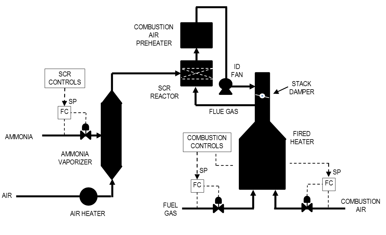
Figure 1 is a simplified process flow diagram of a typical SCR system. A fired heater combusts fuel gas with air to heat a process stream or boil water. The combustion products, commonly called flue gas, leave the heater convection section, and are diverted to the SCR reactor by a stack damper. The SCR reactor utilizes vaporized ammonia and air to reduce the NOx compounds in the flue gas to N2 and water, as described in the above reaction equations.
The flue gas then travels through a combustion air preheater, and from there, to the induced draft (ID) fan. The fan sends the flue gas back to the heater stack above the stack damper. The flue gas then exits the stack and is discharged to the atmosphere.
The heater fuel gas and combustion air are controlled by the heater “combustion controls”, which are described in a separate SAS functional specification. The “SCR controls” adjust the ammonia flow and are described in this functional specification.

Ammonia Requirement Calculation
The flow rate of aqueous ammonia required per SCF of fuel gas fired in the heater can be estimated via the following equation:
NH3 = C * Stoich * (NOx_in – NOx_tgt) * FG (4)
where:
NH3 = Aqueous ammonia flow required (lb/hr).
C = Units conversion factor (lb Aq NH3 per mole NH3).
Stoich = Stoichiometric ratio of NH3 to NOx (typically 1.03).
NOx_in = NOx content of flue gas entering SCR.
NOx_tgt = NOx target for flue gas leaving SCR.
FG = Molar rate of flue gas from fuel gas combustion (lb-moles/hr).
The volumetric fuel gas rate can be compensated for variations in pressure and temperature (if warranted), and then converted to molar rates using an assumed molecular weight. The calculation is used for feedforward control action, as described later in this document.
NOx Target Calculation
The operator-entered target NOx may need to be expressed as the NOx permit limit on a 3% O2 basis. In this case, the setpoint for the control application must be adjusted for the current O2 as follows:
NOx_tgt = NOx@3% * (20.9 – 3.0) / (20.9 – O2_curr) (5)
where:
NOx@3% = Operator-entered NOx setpoint (ppm at 3% O2).
O2_curr = Current flue gas O2 (%).
SCR Control Application
The SCR Ammonia Control application adjusts the aqueous ammonia rate to the SCR to meet the NOx permit limit entered by the operator. The NOx permit limit is converted to the equivalent NOx at the current O2 using equation 5, and the result becomes the setpoint to the NOx feedback controller (AC). The feedback controller output is adjusted for feedforward corrections (+) and then is cascaded to the ammonia flow controller (FC). Figure 2 illustrates the control scheme.
Feedforward action is necessary in this case because of the long response time between a change in the ammonia flow and the SCR outlet NOx analyzer. When changes in the two disturbance variables, fuel gas rate and inlet NOx composition, show up on the outlet NOx analyzer, the analyzer controller will deviate from setpoint until the feedback change to the ammonia rate brings the NOx back to setpoint. The deviation can be reduced by properly implemented feedforward action.

SCR Feedforward Calculation
The feedforward calculation is incremental, meaning that incremental changes in the feedforward inputs become incremental changes to the ammonia flow setpoint. The feedforward action is calculated by taking partial derivatives of equation 4.
ΔNH3_FG = C * Stoich * (NOx_in – NOx_tgt) * ΔFG (6)
ΔNH3_NOX = C * Stoich * FG * ΔNOx_in (7)
ΔNH3_TOT = ΔNH3_FG + ΔNH3_NOX (8)
where:
ΔNH3_FG = Required change in ammonia flow due to change in FG.
ΔNH3_NOX = Required change in ammonia flow due to change in NOx_in.
ΔNH3_TOT = Total feedforward change in ammonia flow.
ΔFG = Change in fuel gas combustion rate.
ΔNOx_in = Change in inlet NOx concentration.
The incremental feedforward algorithm allows the operator to turn on and off the feedforward for each disturbance input without bumping the ammonia flow. Also, the feedforwards can be automatically turned off when the operator puts the fuel gas controller in manual, which indicates that instrument maintenance may about to be performed.
