
Introduction
A Flare Gas Recovery Unit (FGRU) consists of multiple positive-displacement compressors designed to recover gas from the flare header. The controls include starting and stopping the flare gas compressors based on load requirements. The main objectives of the controls are to:
- Maintain flare header pressure control.
- Operate the correct number of compressors for the flare gas load.
- Enforce compressor start permissives.
- Shutdown the compressor(s) when unsafe conditions are detected by the Emergency Shutdown System (ESD).
This document discusses each control objective, identifying the various features that have been incorporated to meet the objective. The reader should also review the following functional specifications on the SAS website:
- DCS-Based Emergency Shutdown System
- DCS-Based Motor Control
These functional specifications provide background on the control objectives and are referred to in this document.
Pressure Control
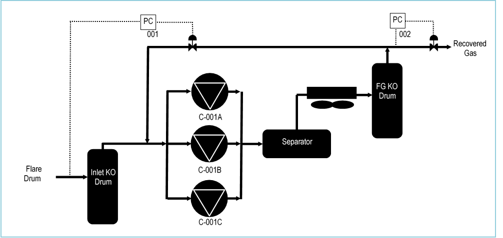
The key process control objective for the FGRU is to maintain control over the pressure in the system. Figure 1 is a simplified schematic of the FGRU pressure controls designed to meet this objective. In this example, the FGRU has three compressors. However, the controls described in this document can handle anywhere from two to six compressors.
figure1The key process control objective for the FGRU is to maintain control over the pressure in the system. Figure 1 is a simplified schematic of the FGRU pressure controls designed to meet this objective. In this example, the FGRU has three compressors. However, the controls described in this document can handle anywhere from two to six compressors.
Suction Pressure Control
One of the main objectives of FGRU pressure control is to match compressor capacity to flare gas load. The FGRU compressors are fixed-speed positive displacement compressors. Therefore, when the flare gas load is low, the compressors can pull a vacuum on the flare system, potentially allowing air intrusion. At high load, the full capacity of the in-service compressors must be made available to recover the flare gas.
Compressor suction pressure indicates the balance between load and capacity. When load exceeds capacity, the flare header pressure increases, and when load is below capacity, the flare header pressure decreases.
To control the compressor capacity, PIC-001 in Figure 1 adjusts a spillback valve that recycles high pressure gas to the compressor suction. PIC-001 must have its setpoint set sufficiently below the flare drum water seal depth to prevent the flare gas from escaping to the flare during normal FGRU operation. The setpoint must also be set high enough to prevent a low suction pressure compressor trip.
Discharge Pressure Control
The DCS includes another pressure controller, PIC-002 in Figure 1, which controls the discharge pressure of the compressors. This controller manipulates the flow of gas out of the Fuel Gas KO Drum and into the recovered fuel gas header. PIC-002 setpoint should be high enough to provide sufficient head to force gas into the recovered fuel gas header and to spill back recycle gas when necessary.
Compressor Start / Stop
Compressor Spillback Valve
The spillback valve that PIC-001 manipulates is the key indicator of the need for compressor capacity. When the valve is nearly closed, a compressor must be started to provide additional capacity. Likewise, when the valve is nearly wide open, a compressor must be stopped to reduce capacity. The desired controllable range for the spillback valve is typically 10 – 65 %.
The compressors can be started or stopped in three different ways:
- Local start/stop.
- DCS manual start/stop.
- Automatic start/stop via DCS logic.
This document details the actions and conditions which will start and stop compressors. The compressor must be in the proper state for starting or stopping. Those states are defined next.
Compressor States
Each compressor can be placed in any one of the following states:
TRIPPED
A compressor goes into the TRIPPED state when any of the ESD trips pertaining to the compressor occurs while it is running. In the TRIPPED state, the compressor is stopped and cannot be re-started. The compressor can exit the TRIPPED state only when all trips clear and the ESD is reset.
STOPPED
A compressor goes into the STOPPED state when all ESD trips are cleared and the ESD is reset. In the STOPPED state, the compressor is not running but can be started manually (either locally or via the DCS).
RUNNING
The operator can transfer a compressor from the STOPPED state to the RUNNING state by starting the compressor either locally or via the DCS. All permissives must be met first, as described in a subsequent section of this document.
AUTO S/S
The operator can transfer a compressor from the STOPPED or RUNNING state to the AUTO S/S (Automatic Start / Stop) state via a button on the process graphic display. In the AUTO S/S state, the compressor is eligible to automatically start and stop as described in a subsequent section of this document. The AUTO S/S state is terminated when the operator manually starts or stops the compressor, or when a trip occurs for that compressor.
Compressor Local Start/Stop
Each compressor has a HAND/OFF/AUTO (HOA) switch in the field. In the hand or off position, the compressor cannot be started via the DCS. In the auto position, the compressor can be started and stopped through the DCS when it is not in the TRIPPED state.
Compressor DCS Manual Start/Stop
Each compressor can be manually started from the DCS graphics, provided that the following start permissives are met:
- Compressor must not be in the TRIPPED state.
- Compressor must have been started no more than three times in the last 60 minutes.
- Compressor must have been stopped for at least 30 seconds (Engineering adjustable).
- DCS stop pushbutton must be off (can be assured by configuring pushbutton as momentary).
- HOA switch must be set to auto.
Each compressor can be manually stopped from the DCS, irrespective of the HOA switch position.
Compressor Automatic Start
The DCS control logic can automatically start a compressor in the AUTO S/S state based on the flare gas loading. The suction pressure controller PIC-001 output, which adjusts the spillback valve, is the key indicator of loading. When the pressure increases to the point that the spillback valve is closed or near to being closed, the full capacity of the in-service compressor is being used. Therefore, another compressor is needed to handle the additional flare gas.
The logic looks for the following conditions to start a compressor (either must be true):
- spillback valve less than 10% open (Engineering adjustable) for least 10 seconds (Engineering adjustable).
- suction pressure above 1.5 psig (Engineering adjustable) for least 10 seconds (Engineering adjustable).
Compressor Starting Order
The control logic determines the compressor starting order based on which compressor has been running the shortest and whether it is in the AUTO S/S state. The logic designates that compressor as the NEXT TO AUTO START and will start it when the conditions are met, as discussed above. The compressor must also meet the automatic start permissives discussed below.
The operator can alter the start selection by taking any compressor out of the AUTO S/S state. The other compressor with the shortest run time will then be started instead, provided it is in the AUTO S/S state and meets the automatic start permissives.
Compressor Automatic Stop
The DCS control logic can automatically stop a compressor in the AUTO S/S state based on the flare gas loading. When multiple compressors are in service and the pressure has fallen to the point that the spillback valve is too far open, then too many compressors are in service. One of the compressors must be taken out of service.
The logic looks for either of the following conditions to stop a compressor:
- spillback valve greater than 65% open (Engineering adjustable) for least 10 seconds (Engineering adjustable).
- suction pressure below 0.2 psig (Engineering adjustable) for least 10 seconds (Engineering adjustable).
Compressor Stopping Order
When multiple compressors are running, the control logic determines the compressor stopping order based on which compressor has been running the longest and whether it is in the AUTO S/S state. The logic designates that compressor as the NEXT TO AUTO STOP and will stop it when the conditions are met, as discussed above. The compressor must also meet the automatic stop permissives discussed below.
The operator can alter the stop selection by taking any compressor out of the AUTO S/S state. The other compressor with the longest run time will then be stopped instead, provided it is in the AUTO S/S state and meets the automatic stop permissives.
Compressor Automatic Start Permissives
The control logic is not permitted to automatically start a compressor unless the following permissives are met:
- All DCS start permissives must be met.
- Compressor must be in the AUTO S/S state.
- PIC-001 must be in automatic mode.
- Compressor must be stopped.
Compressor Automatic Stop Permissives
The control logic is not permitted to automatically stop a compressor unless the following permissives are met:
- Compressor must be in the AUTO S/S state.
- HOA switch must be set to auto.
- Compressor must have been running at least 200 seconds (Engineering adjustable).
Compressor Liquid Ring Water Controls
Each compressor has a solenoid-operated on-off valve that controls the liquid ring (LR) water flow to the liquid seal. The control logic energizes the solenoid to open the valve after the compressor has been running for 8 seconds (as indicated by the run status indicator), and de-energizes the solenoid to close the valve 8 seconds before the compressor stops. In the event of a compressor trip, the compressor stops immediately, not waiting for the valve to close.
Each valve can be manually manipulated by overlay call-up through its associated button on the main process graphic of the DCS, allowing it to be operated independent of the compressor run status. The logic automatically takes control of the valve whenever it needs to open or close the valve.
Compressor Makeup Water Controls
Each compressor has a solenoid-operated on-off valve that controls the makeup water flow to the compressor. The control logic energizes the solenoid to open the valve after the compressor has been started (as indicated by the run status indicator), and de-energizes the solenoid to close the valve when the compressor stops.
Each valve can be manually manipulated by overlay call-up through its associated button on the main process graphic of the DCS, allowing it to be operated independent of the compressor run status. The logic automatically takes control of the valve whenever it needs to open or close the valve.
DCS Implementation
FGRU Sub-Applications
The FGRU controls can be divided into the following sub-applications:
- Compressor Motor Controls (see the DCS-Based Motor Control functional specification on the SAS website for implementation details)
- Motor permissives blocks
- Motor control blocks
- Emergency Shutdown Logic (see the DCS-Based Emergency Shutdown System functional specification on the SAS website for implementation details)
- Voting logic blocks
- ESD trip logic blocks
- First-out indication blocks
- Water Controls
- Start Priority
- Stop Priority
- Auto Start / Stop Logic
The implementation of the last four sub-applications is discussed below.
DCS Implementation – Water Controls
Water Control Blocks
Figure 2 shows the block schematic for the water controls. The blocks are similar for both the LR water and the MU water. The logic for the LR water contains the following blocks (should be executed in this order):
- CIN block for valve closed limit switch (ZSC003).
- CIN block for valve open limit switch (ZSO003).
- CALCA block containing water control logic (HX003).
- GDEV block for water valve open / close command (HY003A).
- COUT block for water valve command (HY003).

Closed Limit Switch 7SC003
ZSC003 is a CIN block that indicates the status of the water valve’s closed limit switch. The valve is closed when the CIN parameter is on.
Open Limit Switch ZSO003
ZSO003 is a CIN block that indicates the status of the water valve’s open limit switch. The valve is open when the CIN parameter is on.
Water Control Logic Block HX003
HX003 is a CALCA block that performs the LR water control logic. The following connections are required:
- BI01 = motor run command or indication
- BI02 = water permissive (lock to 1 if no permissive)
- MA = :HX003.MA.1 (lock to auto)
The block parameters must be set as follows:
- RI01 = water startup delay time (sec)
- TIMINI = 3
- M11 = pulse time (sec) for AUTSW parameter.
The block generates the following outputs:
- BO01 = valve open (1) / or close (0) command to HY003A.AUTDSR
- BO02 = auto command to HY003A.AUTSW
- BO03 = valve command
Note: BI01 should be connected to the BO07 parameter of the motor control logic block when the LR water valve must be closed before the motor is stopped. Typically, the MU water is closed when the motor is stopped so BI01 is connected to the motor run indication.
Water Control Logic Block Steps
STEP01 = IN RI01 ;STARTUP DELAY
STEP02 = OUT M01
STEP03 = AND BI01 BI02 ;COMP RUN & PERMIT
STEP04 = OUT BO03 ;VALVE CMD
STEP05 = OSP M11
STEP06 = IN ~BO03
STEP07 = OSP M11
STEP08 = OR 2
STEP09 = OUT BO02 ;GDEV AUTSW PULSE
STEP10 = CST
STEP11 = IN BO03 ;VALVE CMD
STEP12 = DON M01
STEP13 = OUT BO01 ;GDEV.AUTDSR
STEP14 = END
Water Control Logic Details
Steps 1-2: Store startup delay time (RI01) into M01.
Steps 3-4: Determine the water valve command based on the compressor run indication (BI01) and the permissive (BI02). Store the result to BOO3. Note that the water valve can open only when the permissive allows it to open.
Steps 5-9: The GDEV block’s AUTSW is pulsed on whenever the valve command (BO03) transitions. This feature ensures that the GDEV is in auto whenever the logic needs to change the valve position.
Steps 11-13: Perform a delay on when the valve is commanded open and store the result to BOO1.
Water Valve Open / Close Command Block HY003
HY003 is a GDEV block that opens and closes the water valve and performs command disagree alarming. For example, when the water control logic issues an open request (AUTDSR = 1), the block waits for TOC minutes and then looks for the valve limit switches to indicate whether the valve is open (ZSO003 = 1) and not closed (ZSC003 = 0). If that is not the case, it issues a command disagree alarm, also called a mismatch.
The following connections are required:
AUTDSR = :HX003.BO01
AUTSW = :HX003.BO02
DEVLM1 = :ZSC003.CIN
DEVLM2 = :ZSO003.CIN
The block parameters must be set as follows:
IP_FBM = 0
OP_FBM = 0
AVLLIM1 = 1
AVLLIM2 = 1
TOC = minutes delay before checking for command disagree
DSRTRK = 1
STAT1 = CLOSED
STAT2 = OPEN
STAT3 = CLOSING
STAT4 = OPENING
MM1 = CLOSE FAIL
MM2 = OPEN FAIL
MM3 = UNC CLOSE
MM4 = UNC OPEN
MODE1 = DISABLE
MODE2 = INTLK
MODE3 = MANUAL
MODE4 = HOLD
MODE5 = AUTO
DCS Implementation – Start Priority Logic
Start Priority Logic Blocks
Figure 3 shows the block schematic for the compressor start priority logic. The logic contains the following blocks (should be executed in this order):
- CALCA block that finds lowest compressor run time (PRI_START1).
- CALCA block that determines which compressor has the lowest run time (PRI_START2).

Start Priority Logic Block PRI_START1
PRI_START1 is a CALCA block that finds the lowest compressor run time of all compressors having an auto-start permissive and passes it to the PRI_START2 block. The following connections are required:
RI01 = C-001A run time
RI02 = C-001B run time
RI03 = C-001C run time
BI01 = C-001A auto-start permissive
BI02 = C-001B auto-start permissive
BI03 = C-001C auto-start permissive
BI04 = lock to zero (can be used for future compressor additions)
BI05 = lock to zero (can be used for future compressor additions)
BI06 = lock to zero (can be used for future compressor additions)
MA = :PRI_START1.MA.1 (lock to auto)
The block parameters must be set as follows:
TIMINI = 3
M01 = constant 99999999.
The block generates the following outputs:
RO01 = lowest run time to PRI_START2.RI08.
BO01 = at least 1 compressor with start permissive to PRI_START2.BI16.
Start Priority Block PRI_START1 Steps
STEP01 = IN M01 ;CONSTANT 99999999
STEP02 = OUT RO01 ;LOWEST RUN TIME
STEP03 = CST
STEP04 = OR BI01 BI02 ;PERMISSIVES
STEP05 = OR BI03 BI04 ;PERMISSIVES
STEP06 = OR BI05 BI06 ;PERMISSIVES
STEP07 = OR 3
STEP08 = OUT BO01 ;AT LEAST 1 PERM
STEP09 = BIF 35
STEP10 = CST
STEP11 = IN BI01 ;COMP1 PERMISSIVE
STEP12 = BIF 15
STEP13 = IN RI01 ;COMP1 RUN TIME
STEP14 = OUT RO01 ;LOWEST RUN TIME
STEP15 = IN BI02 ;COMP2 PERMISSIVE
STEP16 = BIF 19
STEP17 = MIN RI02 RO01 ;COMP2 RUN TIME
STEP18 = OUT RO01 ;LOWEST RUN TIME
STEP19 = IN BI03 ;COMP3 PERMISSIVE
STEP20 = BIF 23
STEP21 = MIN RI03 RO01 ;COMP3 RUN TIME
STEP22 = OUT RO01 ;LOWEST RUN TIME
STEP23 = IN BI04 ;COMP4 PERMISSIVE
STEP24 = BIF 27
STEP25 = MIN RI04 RO01 ;COMP4 RUN TIME
STEP26 = OUT RO01 ;LOWEST RUN TIME
STEP27 = IN BI05 ;COMP5 PERMISSIVE
STEP28 = BIF 31
STEP29 = MIN RI05 RO01 ;COMP5 RUN TIME
STEP30 = OUT RO01 ;LOWEST RUN TIME
STEP31 = IN BI06 ;COMP6 PERMISSIVE
STEP32 = BIF 35
STEP33 = MIN RI06 RO01 ;COMP6 RUN TIME
STEP34 = OUT RO01 ;LOWEST RUN TIME
STEP35 = END
Start Priority Block PRI_START1 Logic Details
Steps 1-2: Preload RO01 with 99999999.
Steps 4-9: Determine if any of the compressors have a start permissive. Store the result to BOO1. If false, bypass all subsequent steps.
Steps 11-14: If compressor 1 has a start permissive (BI01), then store this compressor’s run time (RI01) to RO01.
Steps 15-18: If compressor 2 has a start permissive (BI02), then store the lesser of this compressor’s run time (RI02) or RO01 to RO01.
Steps 19-34: Repeat the logic in steps 15-18 for each of the remaining compressors. At the end of the logic, RO01 will contain the lowest compressor run time.
Start Priority Logic Block PRI_START2
PRI_START2 is a CALCA block that determines which compressor has the lowest compressor run time and also has an auto-start permissive. The following connections are required:
RI01 = C-001A run time
RI02 = C-001B run time
RI03 = C-001C run time
RI08 = :PRI_START1.RO01 (lowest run time)
BI01 = C-001A auto-start permissive
BI02 = C-001B auto-start permissive
BI03 = C-001C auto-start permissive
BI04 = lock to zero (can be used for future compressor additions)
BI05 = lock to zero (can be used for future compressor additions)
BI06 = lock to zero (can be used for future compressor additions)
BI16 = :PRI_START1.BO01 (at least 1 compressor with start permissive)
MA = :PRI_START2.MA.1 (lock to auto)
The block parameters must be set as follows:
TIMINI = 3
The block generates the following outputs:
BO01 = C-001A is next to auto start.
BO02 = C-001B is next to auto start.
BO03 = C-001C is next to auto start.
Start Priority Block PRI_START2 Steps
STEP01 = CLR BO01 ;COMP1 NOT NEXT TO START
STEP02 = CLR BO02 ;COMP2 NOT NEXT TO START
STEP03 = CLR BO03 ;COMP3 NOT NEXT TO START
STEP04 = CLR BO04 ;COMP4 NOT NEXT TO START
STEP05 = CLR BO05 ;COMP5 NOT NEXT TO START
STEP06 = CLR BO06 ;COMP6 NOT NEXT TO START
STEP07 = IN BI16 ;ANY COMP START PERM
STEP08 = BIF 50
STEP09 = CST
STEP10 = IN BI01 ;COMP1 PERM
STEP11 = BIF 17
STEP12 = SUB RI01 RI08 ;COMP1 – LOWEST TIME
STEP13 = SSZ BO01 ;COMP1 LOWEST
STEP14 = CLR BO01
STEP15 = IN BO01 ;COMP1 LOWEST?
STEP16 = BIT 50
STEP17 = IN BI02 ;COMP2 PERM
STEP18 = BIF 24
STEP19 = SUB RI02 RI08 ;COMP2 – LOWEST TIME
STEP20 = SSZ BO02 ;COMP2 LOWEST
STEP21 = CLR BO02
STEP22 = IN BO02 ;COMP2 LOWEST?
STEP23 = BIT 50
STEP24 = IN BI03 ;COMP3 PERM
STEP25 = BIF 31
STEP26 = SUB RI03 RI08 ;COMP3 – LOWEST TIME
STEP27 = SSZ BO03 ;COMP3 LOWEST
STEP28 = CLR BO03
STEP29 = IN BO03 ;COMP3 LOWEST?
STEP30 = BIT 50
STEP31 = IN BI04 ;COMP4 PERM
STEP32 = BIF 38
STEP33 = SUB RI04 RI08 ;COMP4 – LOWEST TIME
STEP34 = SSZ BO04 ;COMP4 LOWEST
STEP35 = CLR BO04
STEP36 = IN BO04 ;COMP4 LOWEST?
STEP37 = BIT 50
STEP38 = IN BI05 ;COMP5 PERM
STEP39 = BIF 45
STEP40 = SUB RI05 RI08 ;COMP5 – LOWEST TIME
STEP41 = SSZ BO05 ;COMP5 LOWEST
STEP42 = CLR BO05
STEP43 = IN BO05 ;COMP5 LOWEST?
STEP44 = BIT 50
STEP45 = IN BI06 ;COMP6 PERM
STEP46 = BIF 50
STEP47 = SUB RI06 RI08 ;COMP6 – LOWEST TIME
STEP48 = SSZ BO06 ;COMP6 LOWEST
STEP49 = CLR BO06
STEP50 = END
Start Priority Block PRI_START2 Logic Details
Steps 1-6: Clear BO01 through BO06.
Steps 7-8: Read BI16 to see if any of the compressors have a start permissive. This parameter was obtained from PRI_START1.BO01. If false, skip all subsequent steps.
Steps 10-16: If compressor 1 has a start permissive (BI01), then compare its run time (RI01) to the lowest run time RI08 from PRI_START1.RO01. If it is the lowest, then set BO01 and skip all subsequent steps. If not the lowest, then clear BO01.
Steps 17-49: Repeat the logic in steps 10-16 for each of the remaining compressors.
DCS Implementation – Stop Priority Logic
Stop Priority Logic Blocks
Figure 4 shows the block schematic for the compressor stop priority logic. The logic contains the following blocks (should be executed in this order):
- CALCA block that finds highest compressor run time (PRI_STOP1).
- CALCA block that determines which compressor has the highest run time (PRI_STOP2).

Stop Priority Logic Block PRI_STOP1
PRI_STOP1 is a CALCA block that finds the highest compressor run time of all compressors having an auto-stop permissive and passes it to the PRI_STOP2 block. The following connections are required:
RI01 = C-001A run time
RI02 = C-001B run time
RI03 = C-001C run time
BI01 = C-001A auto-stop permissive
BI02 = C-001B auto-stop permissive
BI03 = C-001C auto-stop permissive
BI04 = lock to zero (can be used for future compressor additions)
BI05 = lock to zero (can be used for future compressor additions)
BI06 = lock to zero (can be used for future compressor additions)
MA = :PRI_STOP1.MA.1 (lock to auto)
The block parameters must be set as follows:
TIMINI = 3
M01 = constant -9999999.
The block generates the following outputs:
RO01 = highest run time to PRI_STOP2.RI08.
BO01 = at least 1 compressor with stop permissive to PRI_STOP2.BI16.
Stop Priority Block PRI_STOP1 Steps
STEP01 = IN M01 ;CONSTANT -9999999
STEP02 = OUT RO01 ;HIGHEST RUN TIME
STEP03 = CST
STEP04 = OR BI01 BI02 ;PERMISSIVES
STEP05 = OR BI03 BI04 ;PERMISSIVES
STEP06 = OR BI05 BI06 ;PERMISSIVES
STEP07 = OR 3
STEP08 = OUT BO01 ;AT LEAST 1 PERM
STEP09 = BIF 35
STEP10 = CST
STEP11 = IN BI01 ;COMP1 PERMISSIVE
STEP12 = BIF 15
STEP13 = IN RI01 ;COMP1 RUN TIME
STEP14 = OUT RO01 ;HIGHEST RUN TIME
STEP15 = IN BI02 ;COMP2 PERMISSIVE
STEP16 = BIF 19
STEP17 = MAX RI02 RO01 ;COMP2 RUN TIME
STEP18 = OUT RO01 ;HIGHEST RUN TIME
STEP19 = IN BI03 ;COMP3 PERMISSIVE
STEP20 = BIF 23
STEP21 = MAX RI03 RO01 ;COMP3 RUN TIME
STEP22 = OUT RO01 ;HIGHEST RUN TIME
STEP23 = IN BI04 ;COMP4 PERMISSIVE
STEP24 = BIF 27
STEP25 = MAX RI04 RO01 ;COMP4 RUN TIME
STEP26 = OUT RO01 ;HIGHEST RUN TIME
STEP27 = IN BI05 ;COMP5 PERMISSIVE
STEP28 = BIF 31
STEP29 = MAX RI05 RO01 ;COMP5 RUN TIME
STEP30 = OUT RO01 ;HIGHEST RUN TIME
STEP31 = IN BI06 ;COMP6 PERMISSIVE
STEP32 = BIF 35
STEP33 = MAX RI06 RO01 ;COMP6 RUN TIME
STEP34 = OUT RO01 ;HIGHEST RUN TIME
STEP35 = END
Stop Priority Block PRI_STOP1 Logic Details
Steps 1-2: Preload RO01 with -9999999.
Steps 4-9: Determine if any of the compressors have an auto-stop permissive. Store the result to BOO1. If false, skip all subsequent steps.
Steps 11-14: If compressor 1 has an auto-stop permissive (BI01), then store this compressor’s run time (RI01) to RO01.
Steps 15-18: If compressor 2 has an auto-stop permissive (BI02), then store the greater of this compressor’s run time (RI02) or RO01 to RO01.
Steps 19-34: Repeat the logic in steps 15-18 for each of the remaining compressors. At the end of the logic, RO01 will contain the highest compressor run time.
Stop Priority Logic Block PRI_STOP2
PRI_STOP2 is a CALCA block that determines which compressor has the highest compressor run time and also has an auto-stop permissive. The following connections are required:
RI01 = C-001A run time
RI02 = C-001B run time
RI03 = C-001C run time
RI08 = :PRI_STOP1.RO01 (highest run time)
BI01 = C-001A auto-stop permissive
BI02 = C-001B auto-stop permissive
BI03 = C-001C auto-stop permissive
BI04 = lock to zero (can be used for future compressor additions)
BI05 = lock to zero (can be used for future compressor additions)
BI06 = lock to zero (can be used for future compressor additions)
BI16 = :PRI_STOP1.BO01 (at least 1 compressor with stop permissive)
MA = :PRI_STOP2.MA.1 (lock to auto)
The block parameters must be set as follows:
TIMINI = 3
The block generates the following outputs:
BO01 = C-001A is next to auto stop.
BO02 = C-001B is next to auto stop.
BO03 = C-001C is next to auto stop.
Stop Priority Block PRI_STOP2 Steps
STEP01 = CLR BO01 ;COMP1 NOT NEXT TO STOP
STEP02 = CLR BO02 ;COMP2 NOT NEXT TO STOP
STEP03 = CLR BO03 ;COMP3 NOT NEXT TO STOP
STEP04 = CLR BO04 ;COMP4 NOT NEXT TO STOP
STEP05 = CLR BO05 ;COMP5 NOT NEXT TO STOP
STEP06 = CLR BO06 ;COMP6 NOT NEXT TO STOP
STEP07 = IN BI16 ;ANY COMP STOP PERM
STEP08 = BIF 50
STEP09 = CST
STEP10 = IN BI01 ;COMP1 PERM
STEP11 = BIF 17
STEP12 = SUB RI01 RI08 ;COMP1 – HIGHEST TIME
STEP13 = SSZ BO01 ;COMP1 HIGHEST
STEP14 = CLR BO01
STEP15 = IN BO01 ;COMP1 HIGHEST?
STEP16 = BIT 50
STEP17 = IN BI02 ;COMP2 PERM
STEP18 = BIF 24
STEP19 = SUB RI02 RI08 ;COMP2 – HIGHEST TIME
STEP20 = SSZ BO02 ;COMP2 HIGHEST
STEP21 = CLR BO02
STEP22 = IN BO02 ;COMP2 HIGHEST?
STEP23 = BIT 50
STEP24 = IN BI03 ;COMP3 PERM
STEP25 = BIF 31
STEP26 = SUB RI03 RI08 ;COMP3 – HIGHEST TIME
STEP27 = SSZ BO03 ;COMP3 HIGHEST
STEP28 = CLR BO03
STEP29 = IN BO03 ;COMP3 HIGHEST?
STEP30 = BIT 50
STEP31 = IN BI04 ;COMP4 PERM
STEP32 = BIF 38
STEP33 = SUB RI04 RI08 ; HIGHEST – HIGHEST TIME
STEP34 = SSZ BO04 ;COMP4 HIGHEST
STEP35 = CLR BO04
STEP36 = IN BO04 ;COMP4 HIGHEST?
STEP37 = BIT 50
STEP38 = IN BI05 ;COMP5 PERM
STEP39 = BIF 45
STEP40 = SUB RI05 RI08 ;COMP5 – HIGHEST TIME
STEP41 = SSZ BO05 ;COMP5 HIGHEST
STEP42 = CLR BO05
STEP43 = IN BO05 ;COMP5 HIGHEST?
STEP44 = BIT 50
STEP45 = IN BI06 ;COMP6 PERM
STEP46 = BIF 50
STEP47 = SUB RI06 RI08 ;COMP6 – HIGHEST TIME
STEP48 = SSZ BO06 ;COMP6 HIGHEST
STEP49 = CLR BO06
STEP50 = END
Stop Priority Block PRI_STOP2 Logic Details
Steps 1-6: Clear BO01 through BO06.
Steps 7-8: Read BI16 to see if any of the compressors have a stop permissive. This parameter was obtained from PRI_STOP1.BO01. If false, skip all subsequent steps.
Steps 10-16: If compressor 1 has a stop permissive (BI01), then compare its run time (RI01) to the highest run time RI08 from PRI_STOP1.RO01. If it is the highest, then set BO01 and skip all subsequent steps. If not the highest, then clear BO01.
Steps 17-49: Repeat the logic in steps 10-16 for each of the remaining compressors.
DCS Implementation – Auto Start/Stop Logic
Auto Start / Stop Logic Blocks
Figure 5 shows the block schematic for the compressor auto start / stop logic. The logic contains the following blocks (should be executed in this order):
- REALM block that signals when the compressor suction pressure is outside of the desired range (PRA001).
- REALM block that signals when the compressor spillback valve is outside of the desired range (ZRA001).
- CALCA block that determines whether a compressor must be started or stopped based on the REALM block outputs (XX001).
- CALCA block that determines the number of compressors that must be running (NUM_COMP).
- CALCA block that determines which compressor must start (AUTO_START).
- CALCA block that determines which compressor must stop (AUTO_STOP).

Suction Pressure REALM Block PRA001
PRA001 is a REALM block that indicates when the compressor suction pressure is outside of the desired range. This block has the following connections:
MEAS = :PI001.MEAS
The block should be locked in auto:
MA = :PRA001.MA.1
The following parameters must be set accordingly:
HLAOPT = 1 (Enables high and low absolute alarming)
HABLIM = Maximum suction pressure
LABLIM = Minimum suction pressure
ABSDB = Alarm deadband to prevent ringing
Spillback Valve REALM Block ZRA001
ZRA001 is a REALM block that indicates when the compressor spillback valve is outside of the desired range. This block has the following connections:
MEAS = :PC001.OUT
The block should be locked in auto:
MA = :ZRA001.MA.1
The following parameters must be set accordingly:
HLAOPT = 1 (Enables high and low absolute alarming)
HABLIM = Maximum spillback valve position
LABLIM = Minimum spillback valve position
ABSDB = Alarm deadband to prevent ringing
Start / Stop Logic Block XX001
XX001 is a CALCA block that determines whether a compressor must be started or stopped based on the REALM block outputs. A compressor must be started when the suction pressure is high or when the spillback valve is low. A compressor must be stopped when the suction pressure is low or when the spillback valve is high. The spillback valve is ignored when the suction pressure controller PC001 is in manual.
The following connections are required:
BI01 = :PRA001.HAIND(suction pressure high)
BI02 = :PRA001.LAIND(suction pressure low)
BI03 = :ZRA001.HAIND(spillback valve high)
BI04 = :ZRA001.LAIND(spillback valve low)
BI05 = :PC001.MA(suction pressure controller in auto)
MA = :XX001.MA.1 (lock to auto)
The block parameters must be set as follows:
TIMINI = 3
M01 = delay time (sec) before issuing start or stop command.
The block generates the following outputs:
BO01 = start command to NUM_COMP.BI15.
BO02 = stop command to NUM_COMP.BI16.
Start / Stop Logic Block XX001 Steps
STEP01 = AND BI05 BI04 ;PC AUTO & VLV LO
STEP02 = OR BI01 ;PRES HI
STEP03 = DON M01 ;DELAY START
STEP04 = OUT BO01 ;START CMND
STEP05 = CST
STEP06 = AND BI05 BI03 ;PC AUTO & VLV HI
STEP07 = OR BI02 ;PRES LO
STEP08 = DON M01 ;DELAY STOP
STEP09 = OUT BO02 ;STOP CMND
STEP10 = END
Start / Stop Logic Block Details
Steps 1-4: If PC001 is in auto (BI05) and its valve is low (BI04), or if the suction pressure is high (BI01), then issue a start command (BO01) after a delay of M01 sec. The delay helps to filter out momentary fluctuations.
Steps 6-9: If PC001 is in auto (BI05) and its valve is high (BI03), or if the suction pressure is low (BI02), then issue a stop command (BO02) after a delay of M01 sec. The delay helps to filter out momentary fluctuations.
Number of Compressors Block NUM_COMP
NUM_COMP is a CALCA block that determines the number of compressors that must be running. The following connections are required:
BI01 = C-001A run indication from motor controls.
BI02 = C-001B run indication from motor controls.
BI03 = C-001C run indication from motor controls.
BI04 = lock to zero (can be used for future compressor additions)
BI05 = lock to zero (can be used for future compressor additions)
BI06 = lock to zero (can be used for future compressor additions)
BI15 = :XX001.BO01 (compressor start command)
BI16 = :XX001.BO02 (compressor stop command)
MA = :NUM_COMP.MA.1 (lock to auto)
The block parameters must be set as follows:
TIMINI = 3
RI08 = timer setpoint (sec) – time required for PIC-001 to respond to latest start or stop.
M01 = timer setpoint stored from RI08.
M02 = maximum number of compressors allowed to run at the same time.
M03 = minimum number of compressors allowed to run at the same time (typically 1).
The block generates the following outputs:
RO01 = number of compressors needed.
RO02 = number of compressors running.
BO01 = start command to AUTO_START.BI16.
BO02 = stop command to AUTO_STOP.BI16.
BO03 = timer running flag.
Number of Compressors Block NUM_COMP Steps
STEP01 = IN RI08 ;TIMER SETPOINT
STEP02 = OUT M01
STEP03 = CST
STEP04 = CLR BO01 ;COMP START FLAG
STEP05 = CLR BO02 ;COMP STOP FLAG
STEP06 = IN BI01 ;COMP 1 RUNNING
STEP07 = IN BI02 ;COMP 2 RUNNING
STEP08 = IN BI03 ;COMP 3 RUNNING
STEP09 = IN BI04 ;COMP 4 RUNNING
STEP10 = IN BI05 ;COMP 5 RUNNING
STEP11 = IN BI06 ;COMP 6 RUNNING
STEP12 = ADD 6
STEP13 = OUT RO02 ;NO. COMPS RUNNING
STEP14 = BII 37
STEP15 = IN BO03 ;TIMER RUNNING
STEP16 = BIT 38
STEP17 = IN RO02 ;NO. COMPS RUNNING
STEP18 = OUT RO01 ;NO. COMPS NEEDED
STEP19 = IN BI15 ;INCR COMPS SIGNAL
STEP20 = BIF 28
STEP21 = INC RO01 ;INCR COMPS NEEDED
STEP22 = SUB M02 RO01 ;MAX <= NEEDED
STEP23 = BIP 26
STEP24 = DEC RO01 ;RESET COMPS NEEDED
STEP25 = GTO 38
STEP26 = SET BO01 ;COMP START CMND
STEP27 = GTO 38
STEP28 = IN BI16 ;DECR COMPS SIGNAL
STEP29 = BIF 38
STEP30 = DEC RO01 ;DECR COMPS NEEDED
STEP31 = SUB RO01 M03 ;NEEDED >= MIN
STEP32 = BIP 35
STEP33 = INC RO01 ;RESET COMPS NEEDED
STEP34 = GTO 38
STEP35 = SET BO02 ;COMP STOP CMND
STEP36 = GTO 38
STEP37 = OUT RO01 ;NO. COMPS NEEDED
STEP38 = OR BO01 BO02 ;START OR STOP CMND
STEP39 = OSP M01
STEP40 = OUT BO03 ;TIMER RUNNING
STEP41 = END
Number of Compressors Block Logic Details
Steps 1-2: Store timer setpoint (RI08) to M01 for use as OSP operand in step 39.
Steps 4-5: Clear start command (BO01) and stop command (BO02).
Steps 6-13: Add run indicators (BI01 – BI06) to obtain total compressors currently running (RO02).
Step 14: Go to step 37 if this is the block initialization pass.
Steps 15-16: Go to step 38 if the timer is running (BO03).
Steps 17-18: Set the number of compressors needed (RO01) equal to the number running (RO02).
Steps 19-20: Go to step 28 if the increase compressors signal (BI15) is false.
Steps 21-23: Increase the number of compressors needed (RO01) and go to step 26 if the number does not exceed the maximum (M02).
Steps 24-23: The number of compressors needed exceeds the maximum, so decrease the number needed (RO01) and go to step 38.
Steps 26-27: Set the compressor start command (BO01) and go to step 38.
Steps 28-29: Go to step 38 if the decrease compressors signal (BI16) is false.
Steps 30-32: Decrease the number of compressors needed (RO01) and go to step 35 if the number is not below the minimum allowed (M03).
Steps 33-34: The number of compressors needed is below the minimum, so increase the number needed (RO01) and go to step 38.
Steps 35-36: Set the compressor stop command (BO02) and go to step 38.
Step 37: This is the block initialization pass so store the number of compressors running to the number needed (RO01).
Steps 38-40: If the start command (BO01) or the stop command (BO02) is true, then do a one-shot pulse (OSP) for M01 seconds and store the result to the timer running signal (BO03).
Auto-Start Logic Block AUTO_START
AUTO_START is a CALCA block that determines which compressor must start. The following connections are required:
BI01 = :PRI_START2.BO01 (C-001A is next to auto start)
BI02 = :PRI_START2.BO02 (C-001B is next to auto start).
BI03 = :PRI_START2.BO03 (C-001C is next to auto start).
BI04 = :PRI_START2.BO04 (can be used for future compressor additions)
BI05 = :PRI_START2.BO05 (can be used for future compressor additions)
BI06 = :PRI_START2.BO06 (can be used for future compressor additions)
BI16 = :NUM_COMP.BO01 (compressor start command)
MA = :AUTO_START.MA.1 (lock to auto)
The block parameters must be set as follows:
TIMINI = 3
The block generates the following outputs:
BO01 = C-001A start command to motor controls.
BO02 = C-001B start command to motor controls.
BO03 = C-001C start command to motor controls.
Auto-Start Logic Block AUTO_START Steps
STEP01 = AND BI01 BI16 ;COMP1 PRI & START REQ
STEP02 = OUT BO01 ;COMP1 START CMND
STEP03 = AND BI02 BI16 ;COMP2 PRI & START REQ
STEP04 = OUT BO02 ;COMP2 START CMND
STEP05 = AND BI03 BI16 ;COMP3 PRI & START REQ
STEP06 = OUT BO03 ;COMP3 START CMND
STEP07 = AND BI04 BI16 ;COMP4 PRI & START REQ
STEP08 = OUT BO04 ;COMP4 START CMND
STEP09 = AND BI05 BI16 ;COMP5 PRI & START REQ
STEP10 = OUT BO05 ;COMP5 START CMND
STEP11 = AND BI06 BI16 ;COMP6 PRI & START REQ
STEP12 = OUT BO06 ;COMP6 START CMND
STEP13 = END
Auto-Start Block AUTO_START Logic Details
Steps 1-2: If compressor 1 is next to start (BI01) and NUM_COMP has issued a start request (BI16), then send a start command (BO01) to the motor controls for that compressor.
Steps 3-12: Repeat the logic in steps 1-2 for each of the remaining compressors.
Auto-Stop Logic Block AUTO_STOP
AUTO_STOP is a CALCA block that determines which compressor must stop. The following connections are required:
BI01 = :PRI_STOP2.BO01 (C-001A is next to auto stop)
BI02 = :PRI_STOP2.BO02 (C-001B is next to auto stop).
BI03 = :PRI_STOP2.BO03 (C-001C is next to auto stop).
BI04 = :PRI_STOP2.BO04 (can be used for future compressor additions)
BI05 = :PRI_STOP2.BO05 (can be used for future compressor additions)
BI06 = :PRI_STOP2.BO06 (can be used for future compressor additions)
BI16 = :NUM_COMP.BO02 (compressor stop command)
MA = :AUTO_STOP.MA.1 (lock to auto)
The block parameters must be set as follows:
TIMINI = 3
The block generates the following outputs:
BO01 = C-001A stop command to motor controls.
BO02 = C-001B stop command to motor controls.
BO03 = C-001C stop command to motor controls.
Auto-Stop Logic Block AUTO_STOP Steps
STEP01 = AND BI01 BI16 ;COMP1 PRI & STOP REQ
STEP02 = OUT BO01 ;COMP1 STOP CMND
STEP03 = AND BI02 BI16 ;COMP2 PRI & STOP REQ
STEP04 = OUT BO02 ;COMP2 STOP CMND
STEP05 = AND BI03 BI16 ;COMP3 PRI & STOP REQ
STEP06 = OUT BO03 ;COMP3 STOP CMND
STEP07 = AND BI04 BI16 ;COMP4 PRI & STOP REQ
STEP08 = OUT BO04 ;COMP4 STOP CMND
STEP09 = AND BI05 BI16 ;COMP5 PRI & STOP REQ
STEP10 = OUT BO05 ;COMP5 STOP CMND
STEP11 = AND BI06 BI16 ;COMP6 PRI & STOP REQ
STEP12 = OUT BO06 ;COMP6 STOP CMND
STEP13 = END
Auto-Stop Block AUTO_STOP Logic Details
Steps 1-2: If compressor 1 is next to stop (BI01) and NUM_COMP has issued a stop request (BI16), then send a stop command (BO01) to the motor controls for that compressor.
Steps 3-12: Repeat the logic in steps 1-2 for each of the remaining compressors.
Graphics Considerations
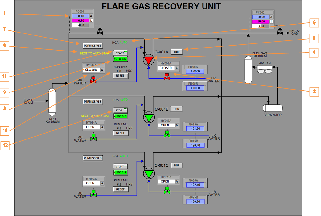
Process Graphic
Figure 6 shows an example of a process graphic for the FGRU Compressors. The following essential items are highlighted by orange arrows connected to numbered boxes:
- Suction pressure controller PIC-001.
- LR water solenoids (green = open; red = closed) and overlay callup.
- MU water solenoids (green = open; red = closed) and overlay callup.
- Compressor run indications (green = run; red = stop).
- HOA Local/Auto status.
- Automatic start / stop priority.
- Permissive overlay callup.
- Trip status (black text = ok; red = tripped) and display callup.
- Auto S/S mode (green = enabled, red = disabled) and overlay callup.
- Compressor run time and reset button.
- DCS start button (light on button indicates DCS start permissive).
- DCS stop button.
DCS Start Button
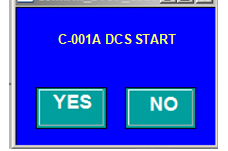
Each stopped compressor can be started from the DCS by clicking the START button on the graphic (see item 11 in Figure 6). The button calls up the start confirmation overlay shown in Figure 7. Click the YES button on the overlay to start the compressor. Click the NO button to cancel the operation and close the overlay.
Note: The light on the button indicates the DCS start permissive (green = ok; red = no).
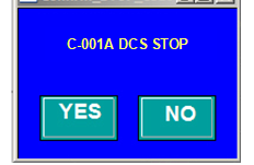
DCS Stop Button
Each running compressor can be stopped from the DCS by clicking the STOP button to call up the stop confirmation overlay shown in Figure 8. Click the YES button on the overlay to stop the compressor. Click the NO button to cancel the operation and close the overlay.
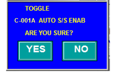
Auto S/S Mode Button
The operator can toggle the AUTO S/S mode by clicking the button on the graphic (see item 9 in Figure 6). The button calls up the confirmation overlay shown in Figure 9. Click the YES button on the overlay to toggle the AUTO S/S state. Click the NO button to cancel the operation and close the overlay.
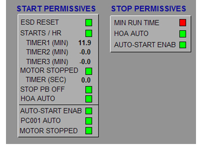
Permissive Button
The operator can call up the permissive overlay by clicking the button on the graphic (see item 7 in Figure 6). A typical permissive overlay is shown in Figure 10.
Run Time Reset Button
The operator can reset the run time counter by clicking the button on the graphic (see item 10 in Figure 6). The button calls up the confirmation overlay shown in Figure 11. Click the YES button on the overlay to reset the run time. Click the NO button to cancel the operation and close the overlay.

Trip Status Button
The operator can call up the trip status display by clicking the TRIP button on the graphic (see item 8 in Figure 6). Trip graphics are discussed in the DCS-Based Emergency Shutdown System functional specification on the SAS website.