Introduction
The DCS is often called upon to start and stop motors, especially compressor motors. The commands can be initiated by the board operator or by logic. In either case, the motor must be protected from potentially damaging conditions.
External systems, like Bentley-Nevada and Multilin, provide motor protection. However, some protection is usually needed at the DCS level as well.
This document describes motor control logic that can be implemented in a Foxboro I/A system.
Objectives
The following objectives must be met by DCS-based motor controls:
- Start and stop motor by operator command via the DCS.
- Stop the motor when a trip is detected, either by the DCS-based Emergency Shutdown System or by any external systems.
- Automatically start and stop motor by DCS-based logic.
- Monitor start permissive conditions and prevent a start from occurring when the permissives are not met.
- When a start command is initiated, monitor the motor run status, and abort the command if the motor does not actually start within a reasonable time limit (commonly called start failure).
- When the motor is started or stopped locally, adjust the DCS outputs to track the run status. This action prevents the reporting of uncommanded starts or stops (commonly called mismatch alarms).
Required Instruments
The following instrumentation is required for DCS-based motor controls:
- Motor start contact output – normally open / pulse on to start motor.
- Motor stop contact output – normally closed / latch off to stop motor. In some cases, the contact can be normally open / latch on to stop motor. The discussion below assumes normally closed contact.
- Motor run status contact input.
- Local HOA status contact input. See below for details.
- Trip status contact input from a DCS-based ESD System or from external systems, such as Triconex, Bentley-Nevada, and/or Multilin.
- Start and stop permissive conditions (analog and/or contact inputs).
Motor Control Wiring
The DCS-based motor control logic is highly dependent on the local motor control wiring. The local controls can consist of start and stop pushbuttons in parallel with the DCS start and stop contacts, or a three-position switch called a hand-off-auto (HOA) switch.
The pushbuttons cause a problem because the DCS logic does not know when the motor has been commanded to start or stop locally. The logic will report that uncommanded starts and stops have occurred. This problem can be mitigated by including a remote/local switch with the pushbuttons, but it requires the local operator to put the switch in local before he can stop the motor. Another alternative is to wire the local pushbuttons to the DCS. Whenever a button is pushed, the logic then knows to sync itself with what is happening locally.
The HOA provides the best interface because its automatic position can be wired to the DCS. The local operator is forced to switch the HOA out of auto when he wants to stop or start the motor locally. When the HOA is not in auto, the DCS motor controls can track the run status to keep in sync. The discussion below assumes that a HOA switch is used.
DCS Starting and Stopping
The board operator can start and stop the motor from the DCS-based graphic displays. Starting occurs when the DCS pushbutton is pulsed on and is subject to the DCS start permissives (discussed below).
The motor is stopped by toggling the DCS stop pushbutton on and is subject to no permissives. The pushbutton must be toggled off to allow the motor to start.
Motor ESD Trip
The motor must be stopped when a trip is detected by the DCS-based ESD System or external trip systems, such as Triconex, Bentley-Nevada, and/or Multilin. The external systems might directly stop the motor, but the motor controls need to know when a trip has happened. The motor cannot be started until the trip has cleared and the ESD has been reset.
Note: The SAS website includes a functional specification entitled “DCS-Based Emergency Shutdown System with First-Out Indication”. The document provides details on building an ESD System in the Foxboro I/A system.
Automatic Starting and Stopping
The motor can be started and/or stopped based on logic in the DCS. Starting is subject to the auto start permissives and stopping is subject to the auto-stop permissives.
Start Permissives
Starting a motor from the DCS must be prevented when potentially adverse conditions prevail. These adverse conditions are called permissives and they must be satisfied to allow a start. Different permissives may be needed for a local start , a DCS start, and an auto-start.
Local start permissives are seldom specified for DCS logic. The permissive result must be wired to the local motor controls. The following are examples of local start permissives:
- ESD system must have been reset (i.e., no trip conditions).
- DCS stop button must be toggled off.
- Motor must have been started less than three times during past hour (no more than three starts per hour allowed – some applications allow only two).
- Motor must have been stopped for at least 30 seconds (adjustable).
Examples of DCS start permissives are:
- All local start permissives.
- HOA must be in auto.
- Another motor has not been started within the previous 10 seconds.
- The number of parallel motors in service does not exceed the maximum allowed.
Examples of auto-start permissives are:
- All DCS start permissives.
- Auto-start enabled.
- A DCS controller that the logic uses to determine when to start or stop the motor is in the proper mode (e.g., automatic).
Stop Permissives
The motor stop permissives apply only to an auto-stop. All DCS and local stops are allowed irrespective of the permissives.
Examples of auto-stop permissives are:
- Motor must have been running at least 30 minutes to cool the motor windings.
- HOA must be in auto.
- Auto-start enabled.
- The number of parallel motors in service will not be below the minimum allowed.
- After this motor is stopped, at least one other motor will be available to start (i.e., meets the auto-start permissives) should it be needed to handle process load changes.
Start Failure
After the motor receives a start command from the DCS, either from the operator or the auto-start logic, the motor run status is monitored. If the motor does not actually run after a predetermined time, then the start failure must be alarmed, and the start command cancelled (commonly called seal-in). In many applications, a start failure is a trip condition.
Uncommanded Starting and Stopping
The motor run status should also be monitored for uncommanded starts or stops. This condition occurs when the run indication disagrees with the commanded state. This failure must be alarmed, but the DCS motor controls seldom can resolve the problem because it indicates that the DCS is not actually controlling the motor.
Motor Run Indication Filter
The motor run status is an important input to the motor controls. If it flickers, the motor logic may shut down the motor, or count the flicker as another start. Therefore, the motor controls include a filter to prevent flickering.
Motor Run Timer
The start and stop permissives require a motor run timer to determine whether the motor has run long enough before stopping. The timer also needs to determine if the motor has been stopped long enough before it can be restarted.
Motor Start Counter
The start permissives often include a start counter to prevent too many starts within a given time period (usually one hour). This permissive is also monitored by the external motor protection system (e.g., Multilin). However, the DCS-based motor control needs to know the status of this permissive to prevent attempting to start a motor that cannot be started. Unfortunately, this permissive in the external motor protection system is seldom made available to the DCS, so the DCS-based motor controls need to count starts as well.
Motor Permissives Implementation
Motor Permissives Logic Blocks
Figure 1 shows the block schematic for a typical motor permissives application. The logic contains the following blocks (should be executed in this order):
- CIN block for trip signal from ESD system (XA001ESD).
- COUT block for DCS stop pushbutton (HS001B).
- CIN block for motor run status (XL001).
- CALCA block for filtering the run status (XX001A).
- CALCA block for monitoring run time (KX001).
- CALCA block for monitoring number of starts (KX001A).
- CIN block for local HOA status (XA001).
- COUT block for auto-start enable (HS001C).
- LOGIC block for start permissives (XX001P1).
- LOGIC block for stop permissives (XX001P2).

DCS Stop Pushbutton Block HS001B
HS001B is a COUT block that provides the operator with a digital pushbutton for stopping the motor. It requires the following connection:
MA = :HS001B.MA.1 (lock in auto)
The block parameters must be set as follows:
IOMOPT = 0
Note: The graphic should set the IN parameter on to stop the motor. The IN parameter must be toggled off to permit a motor start.
Run Status Filter Block XX001A
XX001A is a CALCA block that filters the motor run status to eliminate fluctuations. The following connections are required:
BI01 = :XL001.CIN (motor run status)
MA = :XX001A.MA.1 (lock to auto)
The block parameters must be set as follows:
TIMINI = 3
M01 = Filter delay time (sec)
The following steps are required:
STEP01 = IN BI01 ;RUN IND
STEP02 = DOFF M01
STEP03 = OUT BO01 ;RUN IND FILTERED
STEP04 = END
Run Time Monitor Block KX001
KX001 is a CALCA block that monitors the motor run time. It determines when it is safe to start a motor (minimum stop time) and when it is safe to stop a motor (minimum run time). The following connections are required:
BI01 = :XX001A.BO01 (filtered motor run status)
MA = :KX001.MA.1 (lock to auto)
The block parameters must be set as follows:
PERIOD = 2 (must run at 1 second frequency)
RI01 = Minimum run time (sec)
RI02 = Minimum stop time (sec)
TIMINI = 3
M11 = OSP time (1 sec)
The block generates the following outputs:
BO01 = minimum run time achieved (connect to stop permissive logic)
BO02 = minimum stop time achieved (connect to start permissive logic)
RO01 = countdown timer for minimum run time
RO02 = countdown timer for minimum stop time
Run Time Monitor Block Steps
STEP01 = IN RI01 ;MIN RUN TIME
STEP02 = OUT M01
STEP03 = IN RI02 ;MIN STOP TIME
STEP04 = OUT M02
STEP05 = CST
STEP06 = IN BI01 ;RUN IND
STEP07 = DON M01
STEP08 = OUT BO01 ;MIN RUN TIME FLAG
STEP09 = CST
STEP10 = IN BI01
STEP11 = OSP M11
STEP12 = BIF 16
STEP13 = IN RI01 ;MIN RUN TIME
STEP14 = OUT RO01 ;PRESET TIMER
STEP15 = GTO 22
STEP16 = IN BI01
STEP17 = BIF 21
STEP18 = DEC RO01 ;COUNTDOWN TIMER
STEP19 = IN RO01
STEP20 = BIP 22
STEP21 = CLR RO01 ;CLEAR TIMER
STEP22 = CST
STEP23 = IN BI01
STEP24 = DOFF M02
STEP25 = OUT BO03 ;MIN STOP TIME FLAG
STEP26 = CST
STEP27 = IN ~BI01 ;MOTOR STOPPING
STEP28 = OSP M11
STEP29 = BIF 33
STEP30 = IN RI02 ;MIN STOP TIME
STEP31 = OUT RO02 ;PRESET TIMER
STEP32 = GTO 39
STEP33 = IN BI01
STEP34 = BIT 38
STEP35 = DEC RO02 ;COUNTDOWN TIMER
STEP36 = IN RO02
STEP37 = BIP 39
STEP38 = CLR RO02 ;CLEAR TIMER
STEP39 = CST
STEP40 = OR BI01 ~BO03 ;RUN OR STOPPED
STEP41 = OUT BO02 ;START PERMISSIVE
STEP42 = END
Run Time Monitor Logic Details
Steps 1-4: Store minimum run time (RI01) to M01 and minimum stop time (RI02) to M02. These times will be used in timing steps below. Note: DON and DOFF require time to be in memory variables.
Steps 6-8: Set BOO1 on when the run status (BI01) is on longer than M01 seconds.
Steps 9-21: If the motor is just starting, then store the minimum run time (RI01) to the countdown timer (RO01) and go to step 22. Otherwise, if the motor is running, then decrement the countdown timer. If the timer is negative or the motor not running, then set the timer to zero.
Steps 22-25: Set BOO3 off when the run status (BI01) is off longer than M02 seconds.
Steps 27-38: If the motor is just stopping, then store the minimum stop time (RI02) to the countdown timer (RO02) and go to step 39. Otherwise, if the motor is stopped, then decrement the countdown timer. If the timer is negative or the motor is running, then set the timer to zero.
Steps 39-41: Set BOO2 on when the motor is running (BI01) or when BOO3 is off (indicating that the motor has been stopped longer than the minimum required time).
Motor Starts Counter Block KX001A
KX001A is a CALCA block that monitors the number of motor starts within a specified time period (usually one hour). The following connections are required:
BI01 = :XX001A.BO01 (filtered motor run status)
MA = :KX001A.MA.1 (lock to auto)
The block parameters must be set as follows:
PERIOD = 2 (must run at 1 second frequency)
RI01 = Number of starts monitoring time period – usually locked at 60 minutes
II01 = Maximum starts per time period– must be 1, 2, or 3
TIMINI = 3
M01 = Constant -1.0
M02 = Block execution frequency (should be 1.0)
M03 = Time basis (should be 60 if RI01 is in minutes)
The block generates the following outputs:
BO01 = maximum starts ok (connect to start permissive logic)
RO01 = countdown timer for start 1
RO02 = countdown timer for start 2
RO03 = countdown timer for start 3
IO01 = number of starts in current time period
Motor Starts Counter Block Steps
STEP01 = IN BI01 ;RUN IND
STEP02 = OSP M01 ;OSP 1 EXEC
STEP03 = BIF 18 ;MOTOR START?
STEP04 = IN RO01 ;START1 TIMER
STEP05 = BIP 9 ;TIMER RUNNING?
STEP06 = IN RI01 ;TIMER PRESET
STEP07 = OUT RO01 ;START1 TIMER
STEP08 = GTO 18
STEP09 = IN RO02 ;START2 TIMER
STEP10 = BIP 14 ;TIMER RUNNING?
STEP11 = IN RI01 ;TIMER PRESET
STEP12 = OUT RO02 ;START2 TIMER
STEP13 = GTO 18
STEP14 = IN RO03 ;START3 TIMER
STEP15 = BIP 18 ;TIMER RUNNING?
STEP16 = IN RI01 ;TIMER PRESET
STEP17 = OUT RO03 ;START3 TIMER
STEP18 = CLR IO01 ;CLEAR # STARTS
STEP19 = DIV M02 M03 ;EXEC FREQ / TIME BASIS
STEP20 = OUT M20
STEP21 = IN RO01 ;START1 TIMER
STEP22 = BIN 26 ;TIMER EXPIRED?
STEP23 = SUB M20 ;DECREMENT TIMER
STEP24 = OUT RO01 ;START1 TIMER
STEP25 = INC IO01 ;INCREMENT # STARTS
STEP26 = IN RO02 ;START2 TIMER
STEP27 = BIN 31 ;TIMER EXPIRED?
STEP28 = SUB M20 ;DECREMENT TIMER
STEP29 = OUT RO02 ;START2 TIMER
STEP30 = INC IO01 ;INCREMENT # STARTS
STEP31 = IN RO03 ;START3 TIMER
STEP32 = BIN 36 ;TIMER EXPIRED?
STEP33 = SUB M20 ;DECREMENT TIMER
STEP34 = OUT RO03 ;START3 TIMER
STEP35 = INC IO01 ;INCREMENT # STARTS
STEP36 = IN IO01 ;# STARTS
STEP37 = IN II01 ;MAX # STARTS
STEP38 = SUB
STEP39 = SSN BO01 ;MOTOR START PERMISSIVE
STEP40 = CLR BO01
STEP41 = END
Motor Starts Counter Logic Details
Steps 1-3: Check for motor start. If no start, then go to step 18.
Steps 4-8: If timer for start #1 (RO01) is running (>= 0), then go to step 9. Otherwise, preset the timer to the time period (RI01) and go to step 18.
Steps 9-13: If timer for start #2 (RO02) is running (>= 0), then go to step 14. Otherwise, preset the timer to the time period (RI01) and go to step 18.
Steps 14-17: If timer for start #3 (RO03) is running (>= 0), then go to step 18. Otherwise, preset the timer to the time period (RI01).
Step 18: Initialize the current starts counter (IO01) to zero.
Steps 19-20: Calculate the timer decrement value and store to M20.
Steps 21-25: If timer for start #1 (RO01) has expired (< 0), then go to step 26. Otherwise, decrement the timer by M20 and increment the starts counter (IO01).
Steps 26-30: If timer for start #2 (RO02) has expired (< 0), then go to step 31. Otherwise, decrement the timer by M20 and increment the starts counter (IO01).
Steps 31-35: If timer for start #3 (RO03) has expired (< 0), then go to step 36. Otherwise, decrement the timer by M20 and increment the starts counter (IO01).
Steps 36-40: Subtract the maximum starts (II01) from the current starts counter (IO01). If the result is negative, then set the motor start permissive (BO01) on. Otherwise, clear the motor start permissive.
Start Permissive Logic Block XX001P1
XX001P1 is a LOGIC block that performs a Boolean AND on the various motor start permissive inputs. The following connections are required:
BI01 = :XX001ESD.CIN (motor trip)
BI02 = :KX001A.BO01 (maximum starts)
BI03 = :KX001.BO02 (minimum stop time)
BI04 = :HS001B.COUT.~ (DCS stop pushbutton – reverse input)
BI05 = other local start permissive input (lock to 1 if no other input)
BI06 = :HS001HOA.CIN (HOA in auto)
BI07 = other DCS start permissive input (lock to 1 if no other input)
BI08 = other DCS start permissive input (lock to 1 if no other input)
BI09 = :HS001C.COUT (auto-start enabled)
BI10 = other auto-start permissive input (lock to 1 if no other input)
BI11 = other auto-start permissive input (lock to 1 if no other input)
BI12 = other auto-start permissive input (lock to 1 if no other input)
MA = :XX001P1.MA.1 (lock to auto)
The block generates the following outputs:
BO01 = local start permissive (wire to local motor controls)
BO02 = DCS start permissive (connect to motor control block XX001.BI02)
BO03 = auto-start permissive (connect to motor control block XX001.BI08)
Start Permissive Logic Block Steps
STEP01 = IN BI01 ;ESD CLEAR
STEP02 = AND BI02 ;MAX STARTS
STEP03 = AND BI03 ;MIN STOP TIME
STEP04 = AND BI04 ;DCS STOP BTN OFF
STEP05 = AND BI05 ;PERMISSIVE 5
STEP06 = OUT BO01 ;LOCAL START READY
STEP07 = AND BI06 ;REMOTE (HOA)
STEP08 = AND BI07 ;PERMISSIVE 7
STEP09 = AND BI08 ;PERMISSIVE 8
STEP10 = OUT BO02 ;DCS START READY
STEP11 = AND BI09 ;AUTO S/S
STEP12 = AND BI10 ;PERMISSIVE 10
STEP13 = AND BI11 ;PERMISSIVE 11
STEP14 = AND BI12 ;PERMISSIVE 12
STEP15 = OUT BO03 ;AUTO START READY
Start Permissive Logic Details
Steps 1-6: Perform a Boolean AND on all local start permissives and store to BO01.
Steps 7-10: Perform a Boolean AND on all DCS start permissives (including local start permissives) and store to BO02.
Steps 11-15: Perform a Boolean AND on all auto-start permissives (including local and DCS start permissives) and store to BO03.
Stop Permissive Logic Block XX001P2
XX001P2 is a LOGIC block that performs a Boolean AND on the various motor auto-stop permissive inputs. The following connections are required:
BI01 = :KX001.BO01 (minimum run time)
BI02 = :HS001HOA.CIN (HOA in auto)
BI03 = :HS001C.COUT (auto-start enabled)
BI04 = other auto-stop permissive input (lock to 1 if no other input)
BI05 = other auto-stop permissive input (lock to 1 if no other input)
BI06 = other auto-start permissive input (lock to 1 if no other input)
BI07 = other auto-start permissive input (lock to 1 if no other input)
BI08 = other auto-start permissive input (lock to 1 if no other input)
BI09 = other auto-start permissive input (lock to 1 if no other input)
BI10 = other auto-start permissive input (lock to 1 if no other input)
BI11 = other auto-start permissive input (lock to 1 if no other input)
BI12 = other auto-start permissive input (lock to 1 if no other input)
BI13 = other auto-start permissive input (lock to 1 if no other input)
BI14 = other auto-start permissive input (lock to 1 if no other input)
MA = :XX001P2.MA.1 (lock to auto)
The block generates the following output:
BO01 = auto-start permissive (connect to motor control block XX001.BI09)
Stop Permissive Logic Block Steps
STEP01 = IN BI01 ;MIN RUN TIME
STEP02 = AND BI02 ;REMOTE (HOA)
STEP03 = AND BI03 ;AUTO S/S
STEP04 = AND BI04 ;PERMISSIVE 4
STEP05 = AND BI05 ;PERMISSIVE 5
STEP06 = AND BI06 ;PERMISSIVE 6
STEP07 = AND BI07 ;PERMISSIVE 7
STEP08 = AND BI08 ;PERMISSIVE 8
STEP09 = AND BI09 ;PERMISSIVE 9
STEP10 = AND BI10 ;PERMISSIVE 10
STEP11 = AND BI11 ;PERMISSIVE 11
STEP12 = AND BI12 ;PERMISSIVE 12
STEP13 = AND BI13 ;PERMISSIVE 13
STEP14 = AND BI14 ;PERMISSIVE 14
STEP15 = OUT BO01 ;AUTO STOP PERMIT
Motor Control Implementation
Motor Control Blocks
Figure 2 shows the block schematic for a typical motor control application. The logic contains the following blocks (should be executed in this order):
- COUT block for DCS start (HS001A).
- COUT block for DCS stop (HS001B).
- COUT block for auto-start enable (HS001C).
- CALCA block containing motor control logic (XX001).
- GDEV block for motor start/stop and command disagree alarming (XY001).
- COUT block for motor start command (XS001A).
- CALCA block to latch the motor stop command when necessary (XX001STP).
- COUT block for motor stop command (XS001B).

DCS Start Pushbutton Block HS001A
HS001A is a COUT block that provides the operator with a digital pushbutton for starting the motor. It requires the following connection:
MA = :HS001A.MA.1 (lock in auto)
The block parameters must be set as follows:
IOMOPT = 0
Note: The graphic should momentarily toggle the IN parameter on and then off.
DCS Stop Pushbutton Block HS001B
HS001B is a COUT block that provides the operator with a digital pushbutton for stopping the motor. It requires the following connection:
MA = :HS001B.MA.1 (lock in auto)
The block parameters must be set as follows:
IOMOPT = 0
Note: The graphic should toggle the IN parameter on to stop the motor. The IN parameter must be toggled off to permit a motor start.
Auto Start / Stop Enable Block HS001C
HS001C is a COUT block that provides the operator with a digital pushbutton for enabling auto start / stop of the motor. It requires the following connections:
IN = :HS001C.IN.0 (lock off)
MA = :XX001.BO08 (motor logic puts block into auto to prevent operator from toggling after the motor trips, is manually started or stopped, or when the HOA is not in auto)
The block parameters must be set as follows:
IOMOPT = 0
Note: The graphic should toggle the COUT parameter when the block mode is manual.
Motor Control Logic Block XX001
XX001 is a CALCA block that performs the motor control logic. The following connections are required:
BI01 = :XX001A.BO01 (filtered motor run indication)
BI02 = :XX001P1.BO02 (DCS start permissive)
BI03 = :HS001HOA.CIN (HOA auto status)
BI04 = :HS001A.COUT (DCS start command)
BI05 = :HS001B.COUT (DCS stop command)
BI06 = auto-start command
BI07 = auto-stop command
BI08 = :XX001P1.BO03 (auto-start permissive)
BI09 = :XX001P2.BO01 (auto-stop permissive)
BI10 = :XA001ESD.CIN (reverse if signal = 0 when tripped)
BI11 = :XY001.MMAIND (command disagree alarm from GDEV)
MA = :XX0001.MA.1 (lock to auto)
The block parameters must be set as follows:
TIMINI = 3
M11 = delay time (sec) between stop command and actual motor stop to allow pre-stop actions to occur.
M12 = delay time (sec) between motor stop contact opened and response on the motor run indication.
The block generates the following outputs:
BO01 = motor start (1) / stop (0) command to XY001.AUTDSR
BO02 = motor start command (MRS set)
BO03 = motor stop command (MRS reset)
BO04 = normal stop pulse for M11 seconds
BO05 = delayed stop
BO06 = run delay bypass status
BO07 = undelayed stop (connect to motor pre-stop logic)
BO08 = disable auto-start / stop (connect to HS001C.MA)
Motor Control Logic Block Steps
STEP01 = AND BI06 BI08 ;AUTO START & PERMITTED
STEP02 = AND BI04 BI02 ;DCS START & PERMITTED
STEP03 = AND BI01 ~BI03 ;MOTOR RUNNING & HOA LOC
STEP04 = AND ~M01 ;NOT STOP PULSE
STEP05 = OR 3
STEP06 = OUT BO02 ;START CMD
STEP07 = AND BI03 BI09 ;HOA REM & AUTO STOP PERM
STEP08 = AND BI07 ;AUTO STOP
STEP09 = OR BI05 ;DCS STOP
STEP10 = OUT BO06 ;NORMAL STOP
STEP11 = NOP
STEP12 = AND ~BI01 ~BI03 ;MOTOR STOP & HOA LOC
STEP13 = AND BI11 BO01 ;MISMATCH & RUN CMND
STEP14 = OR 3
STEP15 = OR BI10 ;TRIP
STEP16 = OUT BO03 ;STOP CMD
STEP17 = MRS
STEP18 = OUT BO07 ;UNDELAYED STOP
STEP19 = DOFF M11 ;DELAY
STEP20 = OUT BO05 ;DELAYED STOP
STEP21 = CST
STEP22 = IN BO06 ;NORMAL STOP
STEP23 = OSP M11
STEP24 = OUT BO04 ;NORMAL STOP PULSE
STEP25 = BIT 28
STEP26 = IN BO07 ;UNDELAYED STOP
STEP27 = GTO 29
STEP28 = IN BO05 ;DELAYED STOP
STEP29 = OUT BO01 ;GDEV.AUTDSR
STEP30 = CST
STEP31 = AND BI04 BI02 ;DCS START & PERMITTED
STEP32 = OR BI05 ;DCS STOP
STEP33 = OR BI10 ~BI03 ;TRIP OR HOA LOCAL
STEP34 = OR 2
STEP35 = OUT BO08 ;DISALLOW AUTO S/S
STEP36 = CST
STEP37 = IN M11 ;DELAYED STOP TIME
STEP38 = ADD M12 ;RUN IND RESPONSE TIME
STEP39 = OUT M02
STEP40 = IN BO06 ;NORMAL STOP
STEP41 = OSP M02
STEP42 = OUT M01
STEP43 = END
Motor Control Logic Block Logic Details
Steps 1-6: Perform a Boolean OR on all of the inputs that can start the motor. Note that the auto-start command (BI06) is ANDed with the auto-start permissive (BI08), and the DCS start command (BI04) is ANDed with the DCS start permissive (BI02). In addition, we must track the run indication (BI01) when the HOA is not auto (~BI03). However, when the DCS stop has been initiated, the run indication must be ignored during the delayed stop and for several seconds afterwards. The result is stored in BOO2 which sets the MRS.
Steps 7-10: Determine if a normal stop has been commanded and store the result to BOO6. A normal stop is one that is initiated by a DCS stop command (BI05) OR an auto-stop command (BI07). Note that the auto-stop must be permitted (BI09) and the HOA must be in auto (BI03).
Steps 12-13: The immediate stop command happens when the GDEV block tells us that we have a command disagree (BI11) while we are trying to run the motor (BO01). Also, we must issue a stop command when the motor is not running (~BI01) and the HOA is not auto (~BI03).
Steps 14-16: Perform a Boolean OR on the normal stop command and the immediate stop command. Also, include the trip (BI10) in the logic. The result is stored in BOO3 which resets the MRS.
Steps 17-18: Perform an MRS (master reset) and store the result to BO07. The MRS toggles its output based on the set (BOO2) and reset (BOO3) variables. When the reset is on, the MRS toggles its output off. When the set is on and the reset is off, the MRS toggles its output on. When neither set nor reset is on, the output does not change.
Steps 19-20: Perform a DOFF for M11 seconds and store the result to BO05. In some applications, the motor stop must be delayed until another action is taken. For example, liquid ring compressors require the ring water to be stopped before the motor is stopped.
Steps 22-29: Perform an OSP for M11 seconds and store the result to BO04. If BO04 is on, store the delayed stop BO05 to BO01, which is connected to the GDEV block. If BO04 is off, store the undelayed stop BO07 to BO01.
Steps 31-35: Put the auto-start enable block in auto via BO08 to force it to the disable position and prevent the operator from enabling it. This action becomes necessary when a DCS start or stop is issued, a trip occurs, or the HOA is put into local. The reason for this logic is to prevent an auto-start immediately after the operator has stopped the motor, and an auto-stop immediately after the operator has started the motor.
Steps 37-42: The run indication must be ignored in step 3 during a DCS stop. The required time is the sum of the stop delay time M11 and the run indication response time M12, which is stored into M02. When BO06 pulses on, an OSP is performed for M02 seconds and stored into M01. M01 is used in step 4 to ignore the run indication.
Motor Start/Stop Block XY001
XY001 is a GDEV block that starts and stops the motor and performs command disagree alarming. For example, when the motor control logic issues a start (AUTDSR = 1), the block waits for TOC minutes and then looks for the run indication to show that the motor is running. If not, it issues a command disagree alarm, also called a mismatch.
The following connections are required:
AUTDSR = :XX001.BO01
AUTSW = :XY0001.AUTSW.1 (lock in auto)
DEVLM1 = :XX001A.BO01.~ (filtered run indication – reversed)
DEVLM2 = :XX001A.BO01 (filtered run indication)
The block parameters must be set as follows:
IP_FBM = 0
OP_FBM = 0
AVLIM1 = 1
AVLIM2 = 1
TOC = minutes delay before checking for command disagree
DSRTRK = 1
PLSOPT = 1 (outputs to local motor wiring are pulsed)
PLSTIM = output pulse time (seconds)
STAT1 = STOP
STAT2 = RUN
STAT3 = STOPPING
STAT4 = STARTING
MM1 = STOP FAIL
MM2 = START FAIL
MM3 = UNC STOP
MM4 = UNC START
MODE1 = DISABLE
MODE2 = INTLK
MODE3 = MANUAL
MODE4 = HOLD
MODE5 = AUTO
Motor Stop Output Latch Block XX001STP
XX001STP is a CALCA block that latches the stop output off when the DCS stop pushbutton is on and when a trip occurs. However, the output must be kept on during a delayed stop. The following connections are required:
BI01 = :XY001.COUT_2 (stop command from the GDEV block)
BI02 = :HS001B.COUT.~ (DCS stop pushbutton – reverse input)
BI03 = :XX001.BO05 (stop delay from the motor control logic block)
BI04 = :XA001ESD.CIN (trip)
MA = :XX001STP.MA.1 (lock to auto)
The following steps are required:
STEP01 = OR BI02 BI03 ;DCS STOP OR DELAY OFF
STEP02 = AND BI01 ;GDEV COUT_2
STEP03 = AND BI04 ;ESD
STEP04 = OUT BO01 ;STOP COUT
STEP05 = END
Graphics Considerations
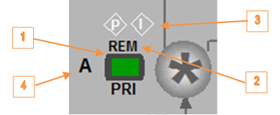
Process Graphic
Figure 3 shows a section of a process graphic containing a compressor motor. The following items / features are highlighted by orange arrows connected to numbered boxes:
- Motor run indication (green = run; red = stop) and overlay call-up.
- HOA status (LOC = local; REM = auto).
- Start permission (P) and SIS interlock (I) diamonds (hollow = ok; red = not ok).
- Auto S/S enable (A = Auto S/S, M = Manual).
Operator Entry DCS Start
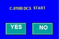
The motor can be manually started from the DCS by clicking on item 1 in Figure 3 to call up its control overlay (Figure 4). Clicking the START button will call up the start overlay shown in Figure 5. Click the YES button on the overlay to start the motor. Click the NO button to cancel the operation and close the overlay.
The motor cannot be started unless the start permissives are met, which is indicated by a diamond next to the motor object (hollow = ok; red = no).
Note: When the start permissives are not all met, the start button is gray indicating that it is not available.
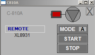
Operator Entry DCS Stop
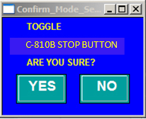
The motor can be manually stopped from the DCS by clicking the STOP button on its control overlay (see Figure 4) to call up the stop overlay in Figure 6. Click the YES button on the overlay to stop the motor. Click the NO button to cancel the operation and close the overlay. The STOP button background on the motor control overlay will turn red.
When the STOP button background is red, it must be toggled off to permit a motor start. Click the button to call up the overlay and click the YES button to allow the motor to start. The STOP button background on the motor control overlay should turn gray.
Operator Entry Auto S/S Enable
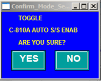
The operator can enable or disable auto-start by clicking the MODE button on its control overlay (see figure 4), which calls up the overlay shown in Figure 7. Click the YES button on the overlay to toggle the auto-start status. Click the NO button to cancel the operation and close the overlay.
Note: When the motor HOA switch is not auto (shown as LOC on display), the mode button is gray indicating that it is not available.
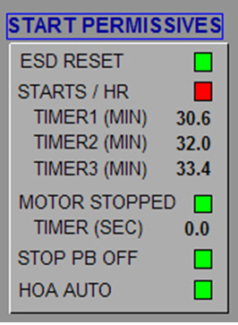
Start Permissives Overlay
Clicking on the diamond P in Figure 3 calls up the start permissives overlay (see Figure 8). In this case, the start permissives are:
- ESD system must have been reset.
- Motor must have been started no more than 3 times per hour (countdown timer for each start shown in overlay).
- Motor must have been stopped for at least 30 seconds (countdown timer shown in overlay).
- The DCS stop pushbutton must be off.
- The HOA must be auto.
The motor cannot be started unless all lights are green.