Introduction
Refineries and petrochemical facilities often include boilers that fire natural gas, refinery fuel gas, liquid fuels, and/or various waste gases to produce steam. The steam enters a header which is connected to the various process units that require steam for heating or as a reactant. The header also receives steam that is generated in process units as well as in parallel boilers.
Steam demand and supply can change suddenly, depending upon operating conditions and upsets anywhere in the steam system. Therefore, the boiler must have effective process controls that set fuel firing to match the changing demand for steam. In addition, the firing must be controlled to provide efficient combustion.
Basic Control Inputs
The following basic control inputs are typically required for implementing boiler control:
- Fuel flow (gas, liquid, waste)
- Combustion air flow
- Combustion air temperature (optional)
- Boiler feed water (BFW) flow
- Steam flow (superheater outlet)
- Steam temperature (superheater outlet)
- Steam pressure (superheater outlet)
- Steam drum level
- Steam drum pressure
- Steam header pressure
- Flue gas oxygen
- Furnace pressure (draft)
Basic Control Outputs
The following basic control outputs are typically required for implementing boiler control:
- Fuel flow control valve(s)
- Forced draft (FD) fan damper and/or speed
- Induced draft (ID) fan damper and/or speed
- BFW flow control valve
- Advanced Applications
Boiler controls typically include the following advanced applications:
- Combustion control
- Plant master control
- Excess air control
- Steam drum level control
- Furnace draft control
These applications are discussed in detail in the remainder of this document.
Combustion Control
Combustion is controlled by adjusting the fuel flow and combustion air flow to meet demand for steam while maintaining the proper ratio of air to fuel. The fuel demand signal from the Boiler Master (discussed in the next section) sets the fuel flow. The combustion air demand signal comes from the air-to-fuel ratio controller, which sets the air flow.
The simplest control scheme would set the fuel flow to meet the demand for steam and set the air flow in ratio to the fuel. However, this scheme has a problem when the boiler is operating at the optimum air-to-fuel ratio, which is where the combustion air rate is just sufficient to provide complete combustion. The slightest negative deviation in the air rate can cause a significant increase in carbon monoxide and/or unburned hydrocarbons. Larger deviations can even result in an explosive mixture.
The solution to this problem is a cross-limiting control scheme (see Figure 1) in which the air rate leads the fuel on a demand increase, and lags the fuel on a demand decrease. Therefore, air is never deficient during load changes. Furthermore, the air demand signal is limited to a minimum air rate to prevent combustion problems at low steam demand.
The key to the cross-limiting control scheme is the “Fuel Override”. It calculates the maximum fuel rate allowed at the current combustion air rate and required air-to-fuel ratio:
MaxFuel = AirRate / Ratio + Bias (1)
where:
AirRate = Combustion air flow rate
Ratio = Air-to-fuel ratio controller setpoint
Bias = Bias to prevent air flow noise from interfering with fuel
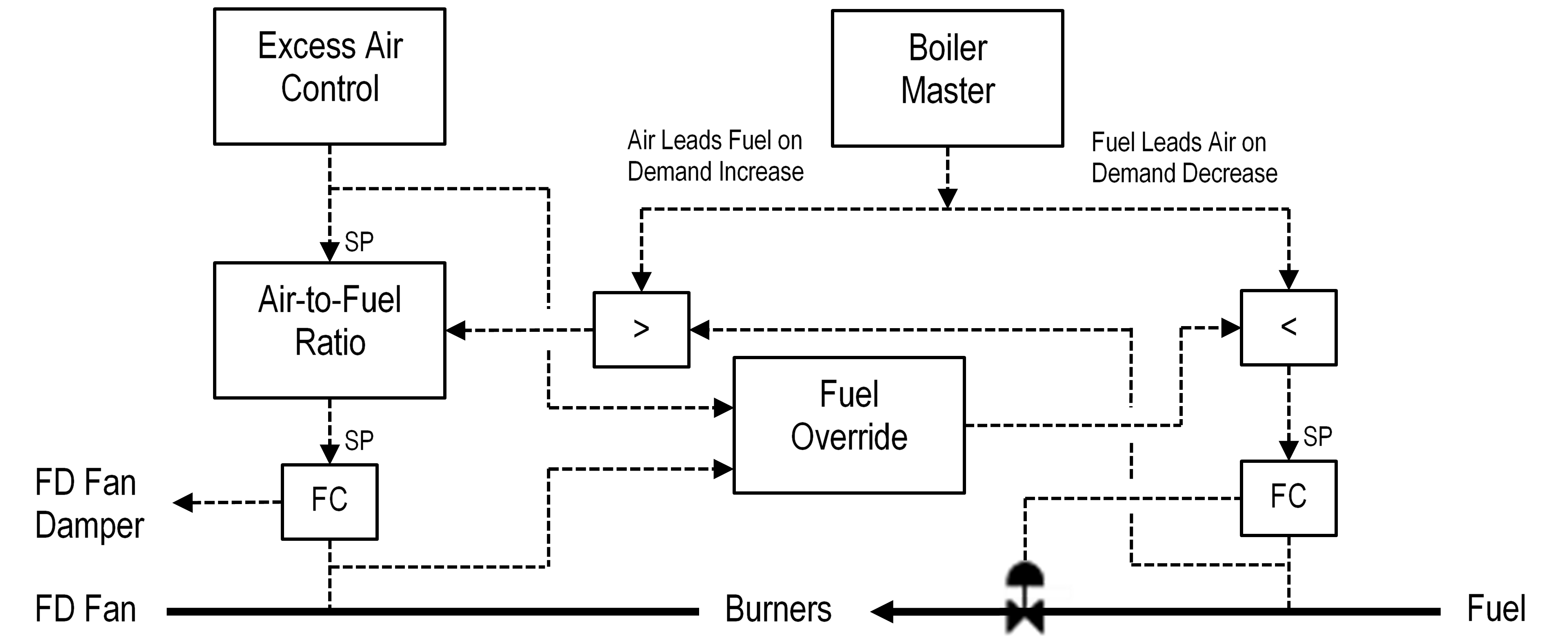
Figure 1: Cross-limiting Combustion Controls
BMS Interface
The control scheme can easily interface with an external Burner Management System (BMS). A typical BMS sends four signals to the combustion controls: boiler trip, purge, light-off, and release-to-modulate. The boiler trip signal tells the boiler controls to close the fuel valve. The purge signal causes the boiler controls to open the FD fan damper. The light-off signal causes the damper and the fuel valve to be set to their light-off positions. The release-to-modulate signal allows the boiler controls to adjust the fuel valve and FD air damper.
Plant Master Control
The Plant Master is a PID controller whose output becomes the fuel demand signal to the combustion controls. The Plant Master utilizes the steam header pressure to indicate the imbalance between steam supply and demand. As steam demand increases, the pressure falls thus indicating that supply must be increased. Conversely, a rising pressure indicates that supply must be reduced to match the current demand.
The Plant Master also includes feedforward control that anticipates changes in the steam demand and pre-adjusts its output to prevent a deviation in the header pressure. Feedforward control is done incrementally, meaning that an incremental change in steam flow is converted into an incremental change in Plant Master output. This approach permits feedforward control to be limited to a reasonable range, and also allows control to be turned off and on bumplessly.
Multiple Parallel Boilers
In multiple parallel boiler arrangements, the Plant Master must output to each boiler’s combustion controls. In this case, each boiler has its own Boiler Master, which is an auto-manual station that accepts the Plant Master’s output, applies a ratio and bias, and sends the result out as the demand signal to the combustion controls. The ratio is used to account for boiler capacity differences. The bias is used to shift load between boilers. A boiler can be base loaded by putting its Boiler Master in manual. Figure 2 shows the Plant Master control scheme.
When outputting to multiple boilers, the Plant Master output’s effect on steam supply depends upon how many Boiler Masters are in automatic. For example, a one-percent change in output has twice the effect on the pressure when the Plant Master is manipulating two boilers than when it is manipulating only one (assuming equal boiler capacities). Therefore, the Plant Master includes adaptive tuning that adjusts both feedback and feedforward control action to match the current number of Boiler Masters in automatic.
The feedforward control scheme can also be expanded in multiple boiler applications to handle load changes in base-loaded boilers. If the base load is changed, the Plant Master output to the remaining cascaded boilers can be pre-adjusted to offset the base load change. Also, the feedforward control can be used to take preemptive action in the event of a boiler trip.
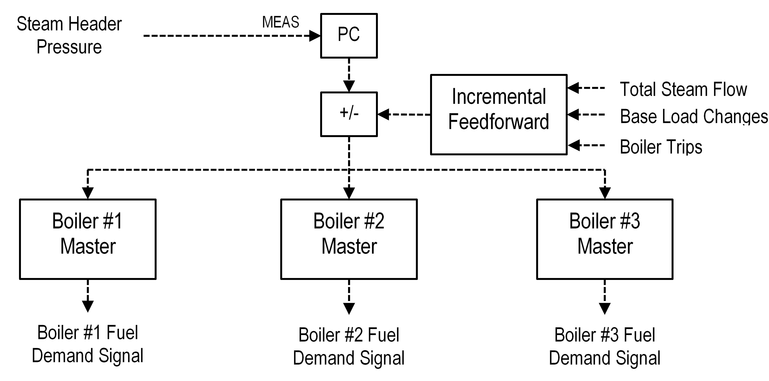
Figure 2: Plant Master / Boiler Master Controls
Excess Air Control
The optimum air-to-fuel ratio can vary greatly, depending primarily upon load, but also upon a number of other potential disturbance variables. The load variation can be programmed into the control system, automatically setting the ratio based upon a load curve. The load curve is established during a test run prior to the commissioning of the boiler controls.
The other disturbance variables are often unmeasurable, so a flue gas oxygen analyzer is usually employed to provide feedback trim control of the air-to-fuel ratio (see Figure 3). The amount of trim can be limited to a reasonable range around the programmed air-to-fuel ratio. The limited trim range helps to prevent bogus analyzer results from driving the ratio too far away from where it ought to be, especially in the downward direction.
The optimum setpoint for the flue gas oxygen controller can also vary with load. Therefore, the setpoint can be programmed versus load as well as the air-to-fuel ratio. The operator can bias the programmed setpoint.
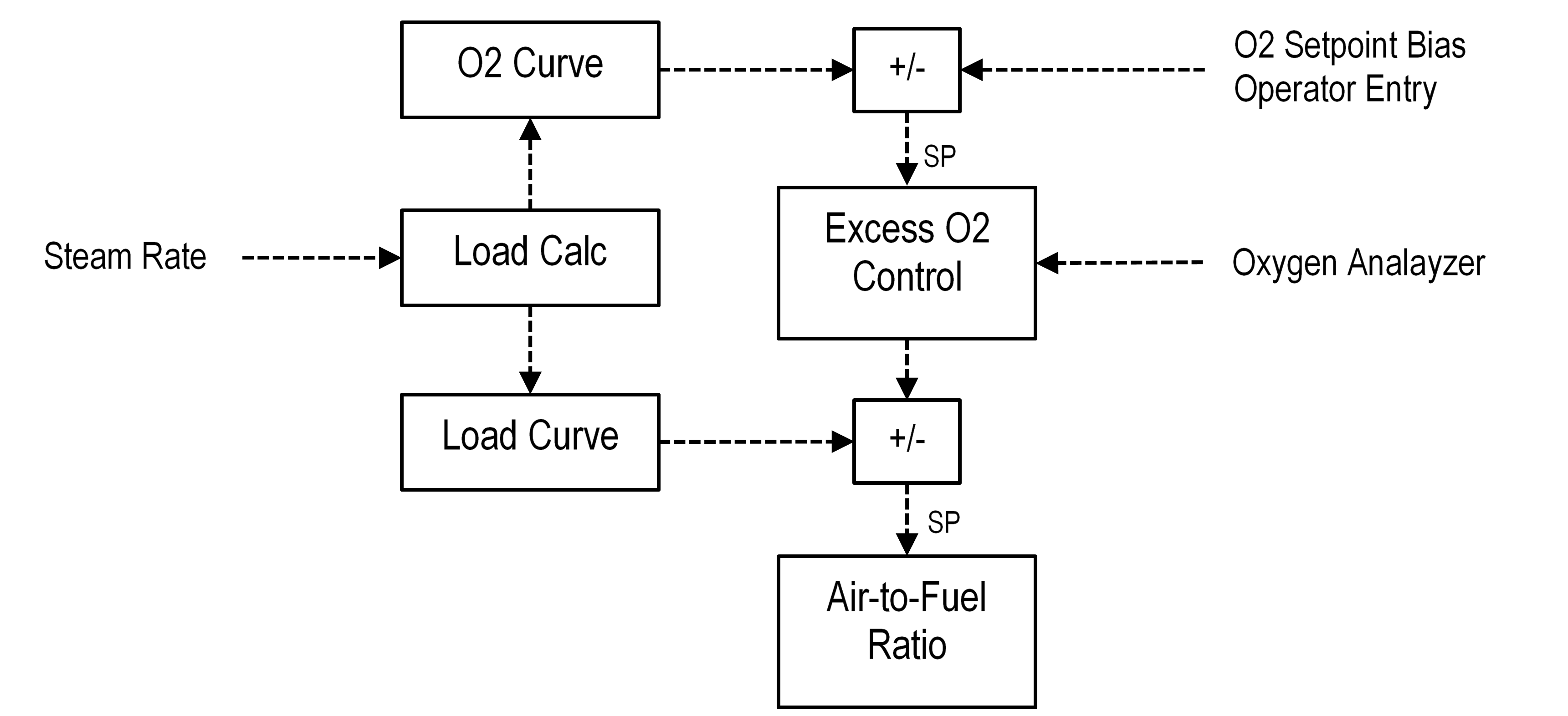
Figure 3: Excess Air Control
Steam Drum Level Control
The steam drum level indicates the flow imbalance between the BFW supply and steam production. Therefore, to maintain BFW inventory, the boiler controls include a steam drum level controller that adjusts the BFW flow.
The level indication can be affected by changes in the steam drum pressure as well as changes in BFW inventory. The pressure changes can cause shrink and swell, which can cause the level controller to adjust the BFW flow in the wrong direction. To mitigate this problem, three-element control is used to pre-adjust the BFW flow for changes in steam production rate (see Figure 4). The level controller then does not need to concern itself with major changes in load and can be detuned somewhat for trim control.
However, a detuned level controller can let the level get away at times. This is especially true at low load. In addition, the steam flow can be erratic at low load. Therefore, the level controller automatically switches between three-element and single-element control (level controller output direct to valve), depending on the load.
Note in Figure 4 that the incremental feedforward approach is also used here. As stated previously, this approach permits feedforward control to be limited to a reasonable range.

Figure 4: Three-Element Steam Drum Level Control
Furnace Pressure Control
The furnace pressure is usually controlled by adjusting the ID fan damper. The draft is also affected by FD fan damper changes caused by the air flow controller. Therefore, the furnace draft controller includes incremental feedforward control to automatically adjust the ID fan damper when the FD fan damper moves (see Figure 5).
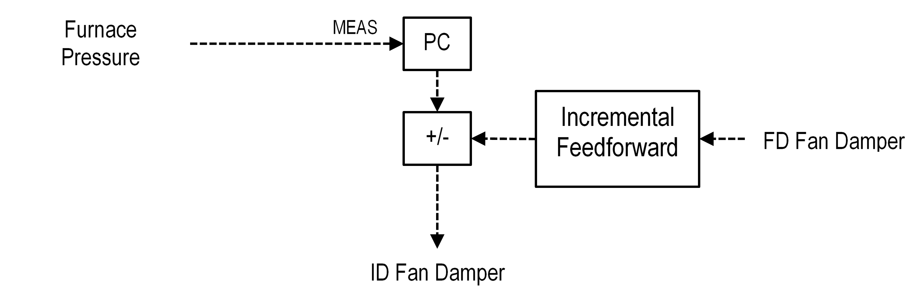
Figure 5: Furnace Pressure Control with Feedforward
Control Enhancements
The following enhancements are often added to the boiler controls discussed above:
- Redundant transmitters for critical inputs
- Fuel BTU compensation
- Multiple fuels
- Combustion air temperature compensation
- FD / ID fan speed control
- Burner pressure overrides
- Boiler Master overrides
Redundant Fuel Flow Transmitters
As shown in Figure 1, the air flow is set by an air-to-fuel ratio controller. If the fuel flow indication were to erroneously decrease, the air flow would be reduced in ratio to the fuel. Therefore, an erroneous fuel flow indication could cause a dangerously low oxygen environment in the furnace.
Control reliability can be increased substantially by utilizing redundant fuel flow transmitters and selecting the higher of the two signals. In the scenario discussed above, the erroneous low signal would be ignored and the air flow would not be adversely affected.
Conversely, if the fuel signal erroneously increases, it would be selected in this case. However, it would lead to an increase in air flow, which is a much safer situation than an erroneous decrease in air flow.
Redundant Air Flow Transmitters
As shown in Figure 1, the air flow is controlled by adjusting the FD Fan damper. If the air flow indication were to erroneously increase, the air flow controller would close the damper. This situation could result in a dangerously low oxygen environment in the furnace.
Control reliability can be increased substantially by utilizing redundant air flow transmitters and selecting the lower of the two signals. In the scenario discussed above, the erroneous high signal would be ignored and the air flow would not be adversely affected.
Conversely, if the air signal erroneously decreases, it would be selected in this case. However, it would lead to an increase in actual air flow, which is a much safer situation than an erroneous decrease in air flow.
Triple Redundant Transmitters
The following signals are vital to the safe operation of the boiler:
- Flue gas oxygen analyzer
- Furnace pressure
- Steam header pressure
Increasing the reliability of the flue gas oxygen indication allows the output limits on the O2 trim controller to be widened. This permits the trim controller to handle fuel BTU excursions better. An erroneous furnace pressure signal in either direction can trip the boiler. Steam header pressure excursions will affect the entire facility, so a reliable signal is essential.
Control reliability can be increased substantially by installing three redundant transmitters for these critical inputs. A middle-of-three selector can then be utilized to pass the middle transmitter input to the control scheme. The middle is used because it protects against a transmitter failing in either direction.
Fuel BTU Compensation
Fuel BTU analysis can be used to compensate the fuel input for heating value excursions. This feature improves Plant Master response to these excursions and also helps the excess air controls maintain the proper air-to-fuel ratio. In this case, the air-to-fuel ratio is calculated in terms of SCF air per BTU fuel, rather than SCF air per SCF fuel gas.
For BTU compensation, the combustion control scheme must be modified as shown in Figure 6.
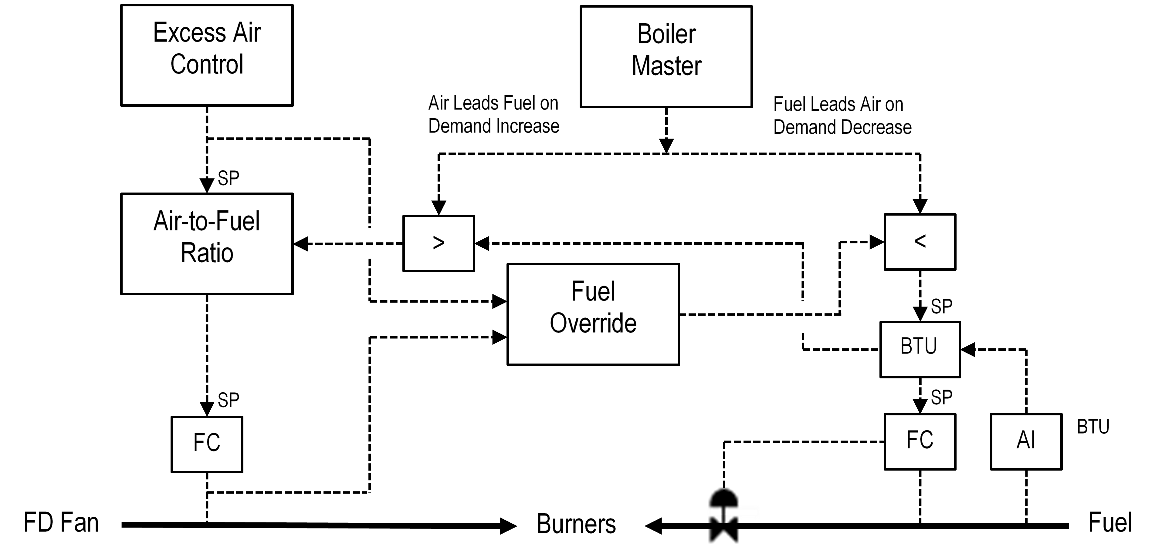
Figure 6: Combustion Controls with Fuel BTU Compensation
Multiple Fuels
If the boiler can fire multiple fuels, then the combustion control scheme must be modified to include those fuels. Figure 7 illustrates the control scheme for three fuels that can be manipulated in cascade and one waste gas stream that is not manipulated. Only one fuel can be in cascade at a time.
Each flow controller setpoint can be adjusted by the combustion controls via its Fuel BTU controller. The Fuel BTU controller obtains the total fired BTU rate from the total fuel BTU calculation and adjusts its flow controller setpoint to meet the total duty demanded by the combustion controls. The duty calculation is performed by converting each fuel flow to BTU rate and summing the individual fuel BTU rates.
The purpose of each BTU controller is to automatically adjust its cascaded fuel for changes in the base-loaded fuels. For example, when the waste gas flow increases, the BTU controller sees the increase in total duty and cuts back the cascaded fuel to offset the waste gas increase.
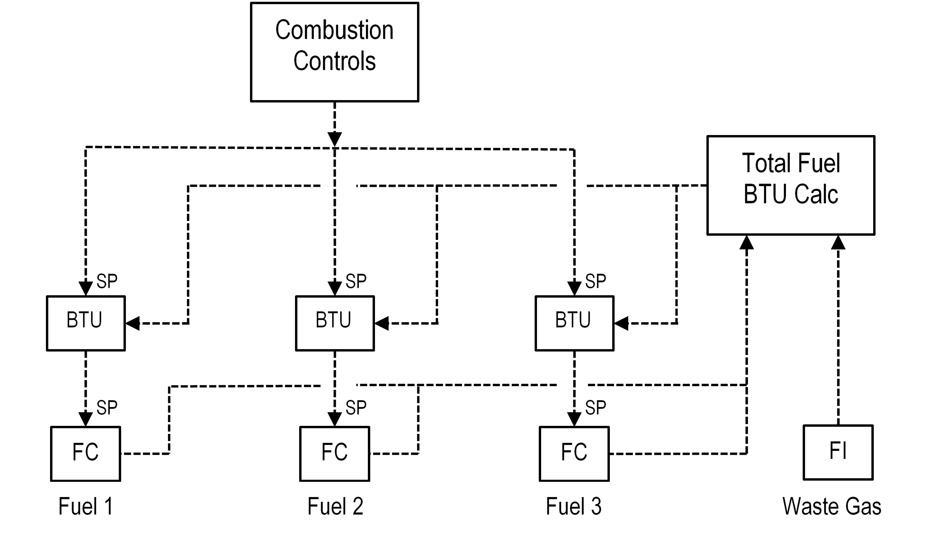
Figure 7: Multiple Fuel Control
Combustion Air Temperature Compensation
In some applications, air flow indication can be affected by significant changes in air preheat. In these cases, air temperature can be used to compensate the air flow based on its effect on air density. The square root compensation equation used for ideal gases can be employed for this application.
FD/ID Fan Speed Control
Figure 1 shows the combustion air flow controller adjusting the FD fan damper. If the fan speed can also be manipulated from the DCS, then the control scheme should include a gap controller (ZC) to adjust the FD fan governor when the damper is outside of the desired operating range (the gap). Figure 8 shows the FD fan governor control scheme.
For example, if the damper position is above the gap, the gap controller will increase the governor speed. The air flow will increase, thus causing the air flow controller to move the damper down into the gap.
Likewise, when the damper position is below the gap, the gap controller will decrease the governor speed. The air flow will decrease, thus causing the air flow controller to move the damper up into the gap.
When the damper position is inside the gap, the gap controller will not change the governor speed.
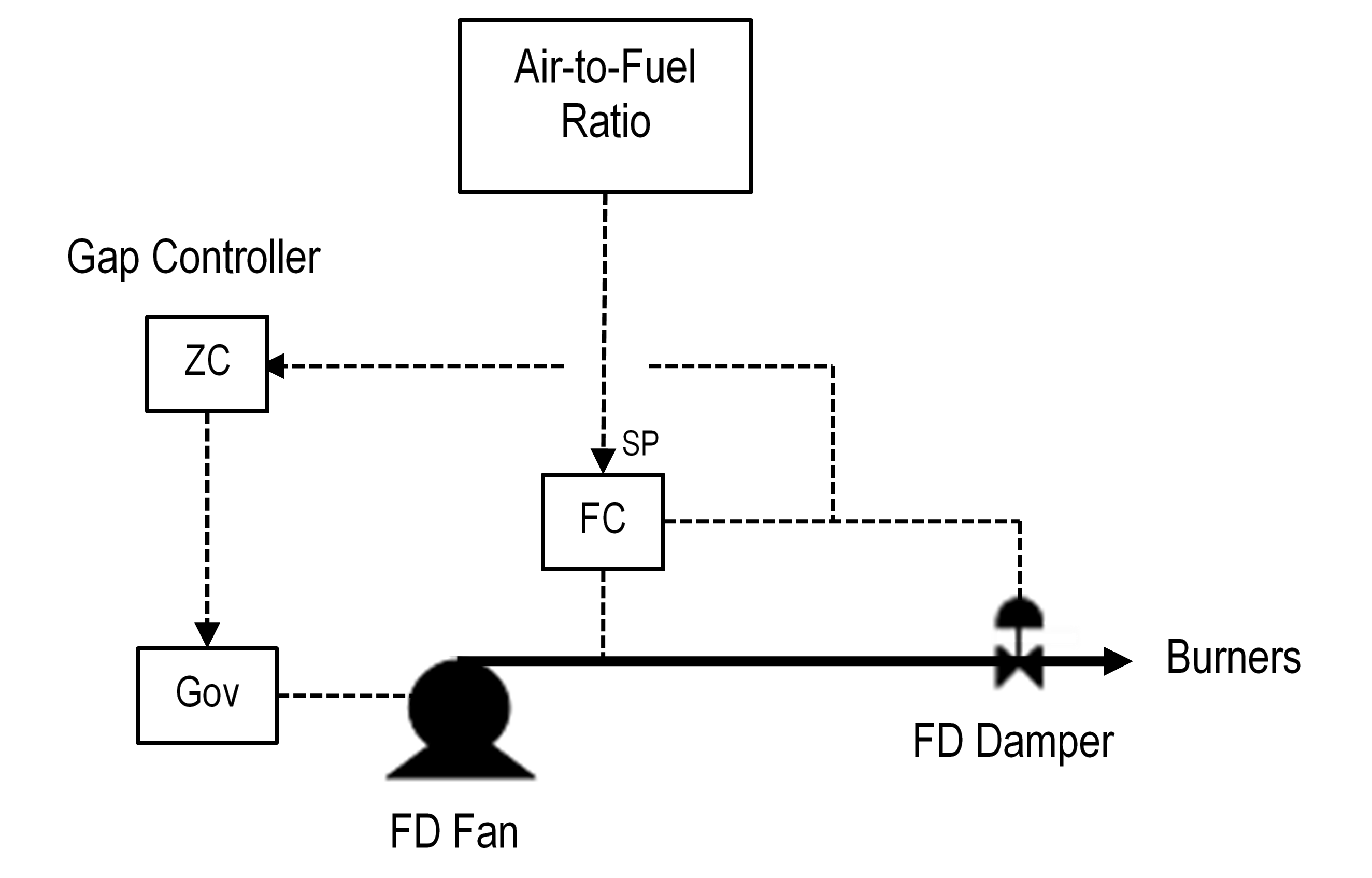
Figure 8: FD Fan Speed Control
Burner Pressure Overrides
Burner pressure overrides can be added to restrict the burner pressure to a high and/or low limit. This feature is designed to prevent the combustion controls from violating the BMS burner pressure trip settings. Figure 9 illustrates the control scheme.
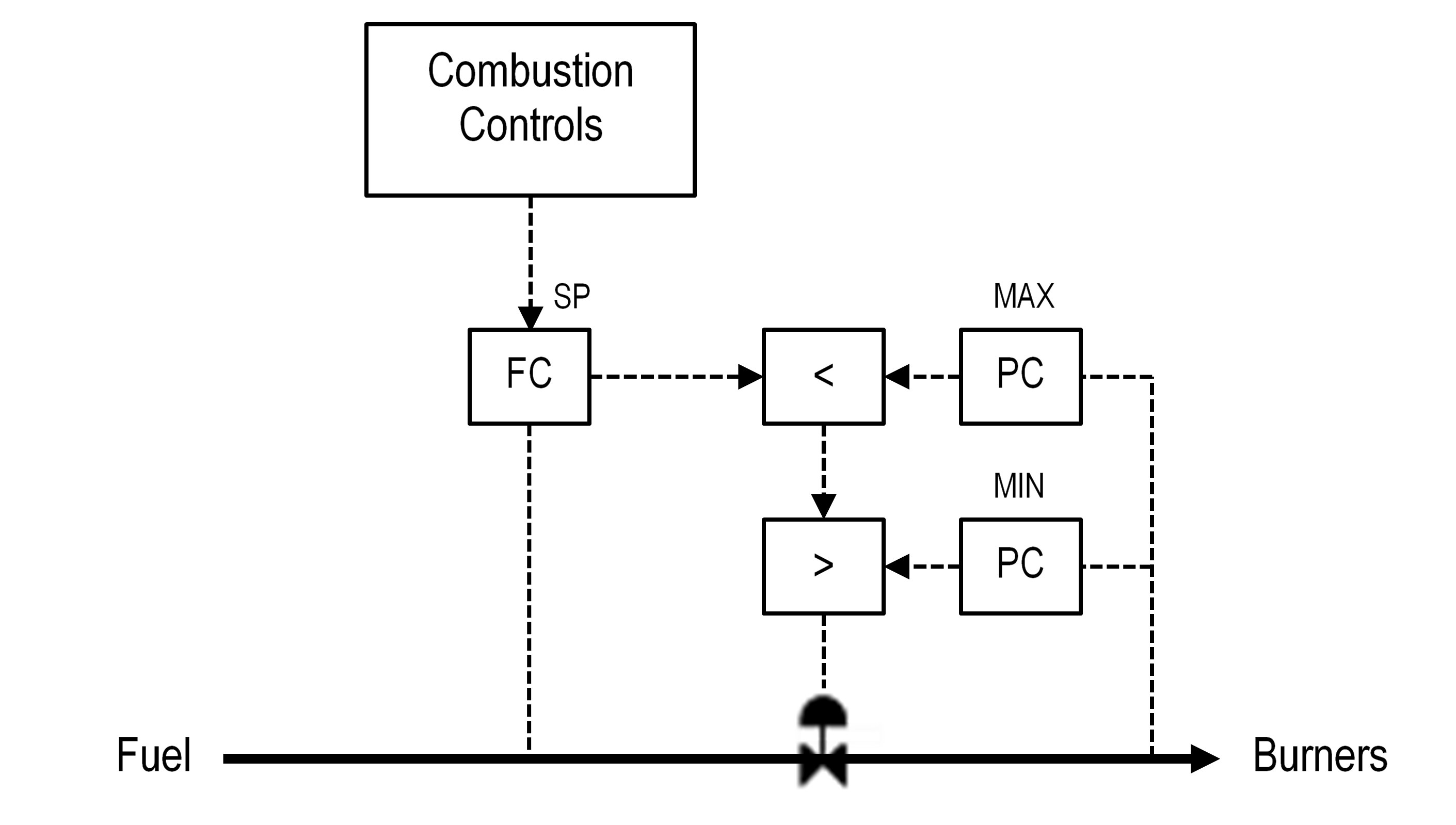
Figure 9: Burner Pressure Overrides
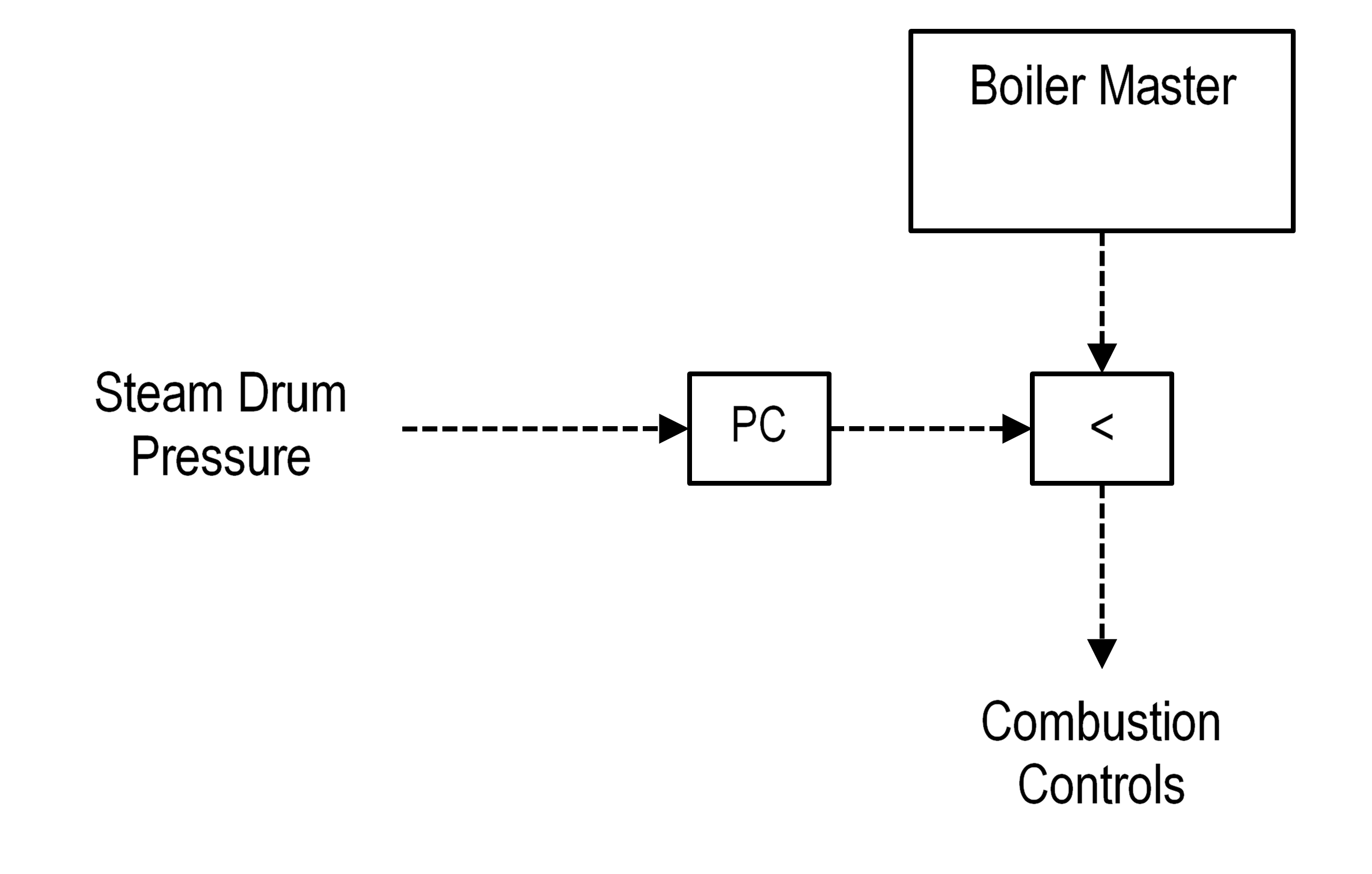
Burner Master Overrides
The Boiler Master can include an override to prevent over-pressuring the steam drum. The steam drum pressure override controller can also be used during startup in lieu of the Plant Master controller. The steam drum pressure controller could be used to set the fuel demand before the boiler is lined up to the steam header. Figure 10 illustrates the control scheme.