Introduction
Orifice meters are used extensively in the Chemical Process Industries to measure flow through pipes. They are relatively inexpensive and reasonably accurate. The flow meter consists of an orifice plate inserted between two flanges in a pipe and a differential pressure (dp) sensor that measures the fluid head loss through the orifice.
The purpose of this post is to describe how the flow is calculated, and how to improve the accuracy of the calculation by compensating for changes in the fluid conditions.
Fluid Flow Through Orifice
The following fluid dynamic equation, which is based on the Bernoulli equation, relates flow in a pipe to the pressure drop across an orifice in the pipe:
q = C * SQRT (h * ρ) (1)
where:
q = flow in SCFM
C = a constant based primarily on orifice geometry
h = fluid head loss through the orifice in inches of water
ρ = fluid density at conditions upstream of orifice
When the orifice meter is designed, the fluid density is obtained for the assumed fluid conditions, usually called design or reference conditions, and an overall meter factor (C’) is calculated:
C’ = C * SQRT (d) (2)
Using the meter factor, equation 1 can be simplified:
q = C’ * SQRT (h) (3)
To obtain the flow, the head from the dp sensor is square-rooted and multiplied by the meter factor. The Foxboro Analog Input block performs this procedure, reading the 4-20 ma signal from the dp transmitter, converting it to head in percent of range, taking the square root, and multiplying by the range, which is the meter factor C’.
General Flow Compensation Equation
The flow equation loses accuracy when the fluid conditions change. Therefore, the flow must be compensated for changes in the fluid conditions. Equation 4a shows how the meter factor is adjusted (C’’) for the actual conditions (a):
C’’ = C * SQRT (ρd) * SQRT (ρa) / SQRT (ρd) (4a)
Simplifying:
C’’ = C’ * SQRT (ρa / ρd) (4b)
Ideal Gas
Ideal Gas Equation
The flow compensation equation requires the determination of the fluid density at actual conditions (a). If the fluid is an ideal gas, then the Ideal Gas Equation can be used to obtain the actual density:
P * V = n * R * T (5)
where:
P = absolute pressure (psia)
V = volume (cuft)
n = moles (lbmoles)
R = Ideal gas constant (10.73 psi-cuft/lbmole-DegR)
T = absolute temperature (DegR)
Equation 5 can be transformed into a more useful equation by converting moles to mass (w) using molecular weight (M):
P * V = (w / M) * R * T (6a)
A further improvement is to convert volume into density (ρ = w / V):
P * M = ρ * R * T (6b)
Rearranging the terms we get a relationship between density and process conditions:
ρ = P * M / (R * T) (6c)
Ideal Gas Properties
We can use Equation 6c only if the fluid is an ideal gas, which must have the following properties:
- The volume of the molecules themselves is negligible compared with the total gas volume.
- No forces act between the molecules of the gas.
Most of the gases found in refineries and petrochemical plants, such as nitrogen, oxygen, and many hydrocarbons, can be assumed to be ideal, provided that the pressure is well below the gas critical pressure. Steam is an exception that is dealt with later in this post.
Ideal Gas Compensation Equation
If the gas acts as an ideal gas, then equation 6c can be substituted into equation 4b:
C’’ = C’ * SQRT [(Pa * M a / T a) / (P d * M d / Td)] (7a)
Rearranging and assuming that the gas molecular weight is constant:
C’’ = C’ * SQRT [(Pa / P d) * (Td / T a)] (7b)
The resulting flow compensation term (Comp) is:
Comp = C’’/ C’ = SQRT [(Pa / P d) * (Td / T a)] (7c)
Ideal Gas Flow Compensation Implementation
The Foxboro I/A CALCA block is used to implement the ideal gas flow compensation calculation. The inputs to the block are the uncompensated flow in standard units (e.g., SCFH, MSCFH, MMSCFD), the fluid pressure upstream of the orifice (typically psig), and the fluid temperature also upstream of the orifice (typically Deg. F). Equation 7c is used to calculate the compensation factor, which is limited to a reasonable range (e.g., 0.8 to 1.2). The resulting factor is then multiplied by the uncompensated, or raw, flow yielding the compensated flow.
Prior to entering the compensation calculation, the pressure and temperature signals are checked for bad status. Two different options are provided for handling the bad signal: 1) use last good value; or 2) use the design value. Option 2 can result in a sudden bump in the signal when the value becomes bad, and also when the value returns to good. Therefore, an initialization pulse can be sent to a flow controller that uses the compensated flow as its measurement input. If the compensated flow is only indicated, then this feature can be ignored.
If the flow signal is bad, then the compensated flow is also marked bad.
Ideal Gas Flow Compensation Block
The ideal gas flow compensation block has the following connections:
RI01 = Flow signal
RI02 = Pressure signal
RI03 = Temperature signal
Also, the block mode should be locked to automatic:
MA = :Blkname.MA.1
The block parameters must be set as follows:
RI07 = Minimum allowed compensation factor (e.g., 0.8).
RI08 = Maximum allowed compensation factor (e.g., 1.2).
BI01 = Bad input handling option (0=use last good value; 1=use design value).
M12 = Design pressure (psia).
M13 = Design temperature (Deg. R).
M14 = Absolute pressure adjustment (e.g., 14.7 for psig input). Set to zero if pressure input is in absolute pressure.
M15 = Absolute temperature adjustment (460 for Deg. F input).
M16 = One-shot pulse time for setting flow controller INITI.
This block has the following outputs:
RO01 = Compensated flow (connect to AIN block for indication or flow controller MEAS).
BO01 = Flow controller initialization pulse (connect to flow controller INITI).
Ideal Gas Flow Compensation Block Steps
STEP01 = RQL RI02 ;BAD PRES INPUT?
STEP02 = OUT BO02 ;PRES STATUS
STEP03 = BIT 6
STEP04 = ADD RI02 M14 ;ABS PRES
STEP05 = GTO 10
STEP06 = BII 9
STEP07 = IN BI01 ;USE REF PRES IF BAD?
STEP08 = BIF 11
STEP09 = IN M12 ;REF PRES
STEP10 = OUT RO03 ;PRES INPUT TO COMP
STEP11 = CST
STEP12 = RQL RI03 ;BAD TEMP INPUT?
STEP13 = OUT BO03 ;TEMP STATUS
STEP14 = BIT 17
STEP15 = ADD RI03 M15 ;ABS TEMP
STEP16 = GTO 21
STEP17 = BII 20
STEP18 = IN BI01 ;USE REF TEMP IF BAD?
STEP19 = BIF 22
STEP20 = IN M13 ;REF TEMP
STEP21 = OUT RO04 ;TEMP INPUT TO COMP
STEP22 = CST
STEP23 = DIV RO03 M12 ;ABS PRES / REF PRES
STEP24 = DIV M13 RO04 ;REF TEMP / ABS TEMP
STEP25 = MUL 2
STEP26 = SQRT
STEP27 = IN RI07 ;MIN COMP FACTOR
STEP28 = IN RI08 ;MAX COMP FACTOR
STEP29 = MEDN
STEP30 = OUT RO02 ;COMP FACTOR
STEP31 = MUL RI01 ;FLOW INPUT
STEP32 = OUT RO01 ;COMPENSATED FLOW
STEP33 = CST
STEP34 = RQL RI01 ;FLOW BAD?
STEP35 = BIT 38
STEP36 = CBD RO01 ;CLEAR BAD STATUS
STEP37 = GTO 39
STEP38 = SBD RO01 ;SET BAD STATUS
STEP39 = CST
STEP40 = IN BO02 ;PRES BAD
STEP41 = OSP M16
STEP42 = IN ~BO02 ;PRES GOOD
STEP43 = OSP M16
STEP44 = IN BO03 ;TEMP BAD
STEP45 = OSP M16
STEP46 = IN ~BO03 ;TEMP GOOD
STEP47 = OSP M16
STEP48 = OR 4
STEP49 = OUT BO01 ;TRANSITION PULSE TO INIT
STEP50 = END
Flow Compensation Logic Details
Steps 1-10: The pressure input is checked for bad status. If bad, BI01 determines whether the last good value (0) or the design value (1) is used. If the value is good, then the pressure is converted to absolute pressure by adding M14 and the result is stored in RO03.
Steps 12-21: The temperature input is checked for bad status. If bad, BI01 determines whether the last good value (0) or the design value (1) is used. If the value is good, then the temperature is converted to absolute temperature by adding M15 and the result is stored in RO04.
Steps 23-32: Equation 7c is used to calculate the compensation factor. The factor is then limited to a maximum (RI08) and minimum (RI07), and the result is stored in RO02. The factor is multiplied by the flow input and the resulting compensated flow is stored in RO01.
Steps 34-38: The flow input is checked for bad status. If the flow is bad, the compensated flow in RO01 is marked bad. Otherwise, the bad status is cleared for RO01.
Steps 40-49: The bad status flags BO02 and BO03 are checked for a transition from good to bad and from bad to good. If the status has changed, then the controller initialization trigger BO01 is pulsed on for M16 seconds.
Superheated Steam
Superheated Steam Flow Compensation
Steam is definitely not an ideal gas. Water is a polar molecule which attracts other water molecules via hydrogen bonding. This feature violates the ideal gas condition that no forces act between the molecules of the gas. Therefore, we must fall back on the more general flow compensation equation 4b.
In the case of steam, specific volume (v) is used instead of density, which is the inverse of specific volume:
v = 1 / ρ (8a)
Substituting equation 8a into equation 4b, we obtain:
C’’ = C’ * SQRT (vd / va) (8b)
where:
vd = steam specific volume at design pressure and temperature.
va = steam specific volume at actual pressure and temperature.
Steam Specific Volume Lookup
The specific volume data is obtained from steam tables. The two-parameter lookup (i.e., pressure and temperature) is simplified by splitting the operation into two separate single-parameter lookups:
- Look up specific volume at actual pressure and design temperature (vp).
- Calculate compensation factor (Comp_P) by dividing vd by vp.
- Look up specific volume at actual temperature and design pressure (vt).
- Calculate compensation factor (Comp_T) by dividing vd by vt.
- Calculate overall compensation factor by multiplying Comp_P and Comp_T.
Superheated Steam Flow Compensation Implementation
Figure 1 shows the block schematic for superheated steam flow compensation. A CHARC block is used to characterize the actual pressure vs. the corresponding compensation factor Comp_P, and another CHARC block is used to characterize the actual temperature vs. the corresponding compensation factor Comp_T. A CALCA block is used to multiply the two compensation factors and the raw flow to obtain the compensated flow. The CALCA block steps are similar to those for the ideal gas compensation.
Prior to entering the compensation calculation, the pressure and temperature signals are checked for bad status. Two different options are provided for handling the bad signal: 1) use last good value; or 2) use the design value. Option 2 can result in a sudden bump in the signal when the value becomes bad, and also when the value returns to good. Therefore, an initialization pulse can be sent to a flow controller that uses the compensated flow as its measurement input. If the compensated flow is only indicated, then this feature can be ignored.
If the flow signal is bad, then the compensated flow is also marked bad.
Figure 1: Block Schematic for Steam Flow Compensation
Steam Pressure Compensation CHARC Block PY0002
The steam pressure compensation block contains the table of pressure vs. compensation factor Comp_P. The values shown are for a design pressure of 400 psig and design temperature of 600 Deg. F:
X_1 = 5.3 Y_1 = 0.213
X_2 = 10.3 Y_2 = 0.238
X_3 = 15.3 Y_3 = 0.261
X_4 = 20.3 Y_4 = 0.282
X_5 = 25.3 Y_5 = 0.302
X_6 = 30.3 Y_6 = 0.320
X_7 = 35.3 Y_7 = 0.337
X_8 = 40.3 Y_8 = 0.354
X_9 = 50.3 Y_9 = 0.385
X_10 = 65.3 Y_10 = 0.428
X_11 = 85.3 Y_11 = 0.479
X_12 = 105.3 Y_12 = 0.525
X_13 = 145.3 Y_13 = 0.609
X_14 = 185.3 Y_14 = 0.683
X_15 = 235.3 Y_15 = 0.767
X_16 = 285.3 Y_16 = 0.843
X_17 = 385.3 Y_17 = 0.982
X_18 = 435.3 Y_18 = 1.047
X_19 = 485.3 Y_19 = 1.109
X_20 = 535.3 Y_20 = 1.169
X_21 = 585.3 Y_21 = 1.227
Also, the block mode should be locked to automatic:
MA = :PY0002.MA.1
The block output is the compensation factor Comp_P at the actual pressure. It is sent to the CALCA block.
Steam Temperature Compensation CHARC Block TY0003
The steam temperature compensation block contains the table of temperature vs. compensation factor Comp_T. The values shown are for a design pressure of 400 psig and design temperature of 600 Deg. F:
X_1 = 448 Y_1 = 1.127
X_2 = 450 Y_2 = 1.124
X_3 = 460 Y_3 = 1.113
X_4 = 480 Y_4 = 1.092
X_5 = 500 Y_5 = 1.074
X_6 = 520 Y_6 = 1.056
X_7 = 540 Y_7 = 1.041
X_8 = 550 Y_8 = 1.033
X_9 = 560 Y_9 = 1.026
X_10 = 580 Y_10 = 1.013
X_11 = 600 Y_11 = 1.000
X_12 = 620 Y_12 = 0.988
X_13 = 640 Y_13 = 0.977
X_14 = 650 Y_14 = 0.972
X_15 = 660 Y_15 = 0.966
X_16 = 680 Y_16 = 0.956
X_17 = 700 Y_17 = 0.945
X_18 = 720 Y_18 = 0.936
X_19 = 750 Y_19 = 0.922
X_20 = 800 Y_20 = 0.901
X_21 = 900 Y_21 = 0.863
Also, the block mode should be locked to automatic:
MA = :TY0003.MA.1
The block output is the compensation factor at the actual temperature. It is sent to the CALCA block.
Superheated Steam Flow Compensation Block FY0001
The superheated steam flow compensation block has the following connections:
RI01 = Flow signal
RI02 = Pressure compensation input from :PY0002.OUT
RI03 = Temperature compensation input from :TY0003.OUT
Also, the block mode should be locked to automatic:
MA = :FY0001.MA.1
The block parameters must be set as follows:
RI07 = Minimum allowed compensation factor (e.g., 0.8).
RI08 = Maximum allowed compensation factor (e.g., 1.2).
BI01 = Bad input handling option (0=use last good value; 1=use design value).
M11 = Design compensation factor (1.0).
M16 = One-shot pulse time for setting flow controller INITI.
This block has the following outputs:
RO01 = Compensated flow (connect to AIN block for indication or flow controller MEAS).
BO01 = Flow controller initialization pulse (connect to flow controller INITI).
Superheated Steam Flow Compensation Block Steps
STEP01 = RQL RI02 ;BAD PRES FACTOR?
STEP02 = OUT BO02 ;PRES STATUS
STEP03 = BIT 6
STEP04 = IN RI02 ;PRES COMP FACTOR
STEP05 = GTO 10
STEP06 = BII 9
STEP07 = IN BI01 ;USE REF PRES IF BAD?
STEP08 = BIF 11
STEP09 = IN M11 ;1.0
STEP10 = OUT RO03 ;PRES FACTOR TO COMP
STEP11 = CST
STEP12 = RQL RI03 ;BAD TEMP FACTOR?
STEP13 = OUT BO03 ;TEMP STATUS
STEP14 = BIT 17
STEP15 = IN RI03 ;TEMP COMP FACTOR
STEP16 = GTO 21
STEP17 = BII 20
STEP18 = IN BI01 ;USE REF TEMP IF BAD?
STEP19 = BIF 22
STEP20 = IN M11 ;1.0
STEP21 = OUT RO04 ;TEMP FACTOR TO COMP
STEP22 = CST
STEP23 = MUL RO03 RO04 ;P FACTOR * T FACTOR
STEP24 = IN RI07 ;MIN COMP FACTOR
STEP25 = IN RI08 ;MAX COMP FACTOR
STEP26 = MEDN
STEP27 = OUT RO02 ;COMP FACTOR
STEP28 = MUL RI01 ;FLOW INPUT
STEP29 = OUT RO01 ;COMPENSATED FLOW
STEP30 = CST
STEP31 = RQL RI01 ;FLOW BAD?
STEP32 = BIT 35
STEP33 = CBD RO01 ;CLEAR BAD STATUS
STEP34 = GTO 36
STEP35 = SBD RO01 ;SET BAD STATUS
STEP36 = CST
STEP37 = IN BO02 ;PRES BAD
STEP38 = OSP M16
STEP39 = IN ~BO02 ;PRES GOOD
STEP40 = OSP M16
STEP41 = IN BO03 ;TEMP BAD
STEP42 = OSP M16
STEP43 = IN ~BO03 ;TEMP GOOD
STEP44 = OSP M16
STEP45 = OR 4
STEP46 = OUT BO01 ;TRANSITION PULSE TO INIT
STEP47 = END
Superheated Steam Flow Compensation Logic Details
Steps 1-10: The pressure compensation factor is checked for bad status. If bad, BI01 determines whether the last good value (0) or the design value (1) is used. If the value is good, then the factor is stored in RO03.
Steps 12-21: The temperature compensation factor is checked for bad status. If bad, BI01 determines whether the last good value (0) or the design value (1) is used. If the value is good, then the factor is stored in RO04.
Steps 23-29: The overall compensation factor is calculated by multiplying the pressure compensation factor and the temperature compensation factor. The result is then limited to a maximum (RI08) and minimum (RI07) and stored in RO02. The factor is multiplied by the flow input and the resulting compensated flow is stored in RO01.
Steps 31-35: The flow input is checked for bad status. If the flow is bad, the compensated flow in RO01 is marked bad. Otherwise, the bad status is cleared for RO01.
Steps 37-46: The bad status flags BO02 and BO03 are checked for a transition from good to bad and from bad to good. If the status has changed, then the controller initialization trigger BO01 is pulsed on for M16 seconds.
Steam Flow Compensation Excel Spreadsheet
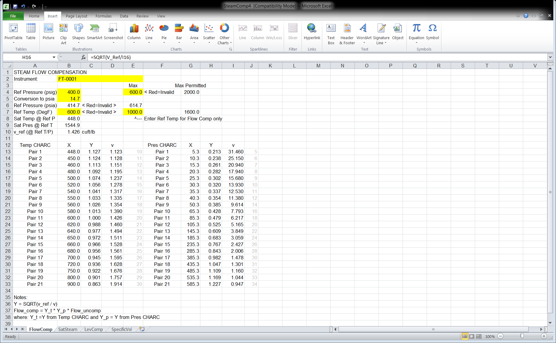
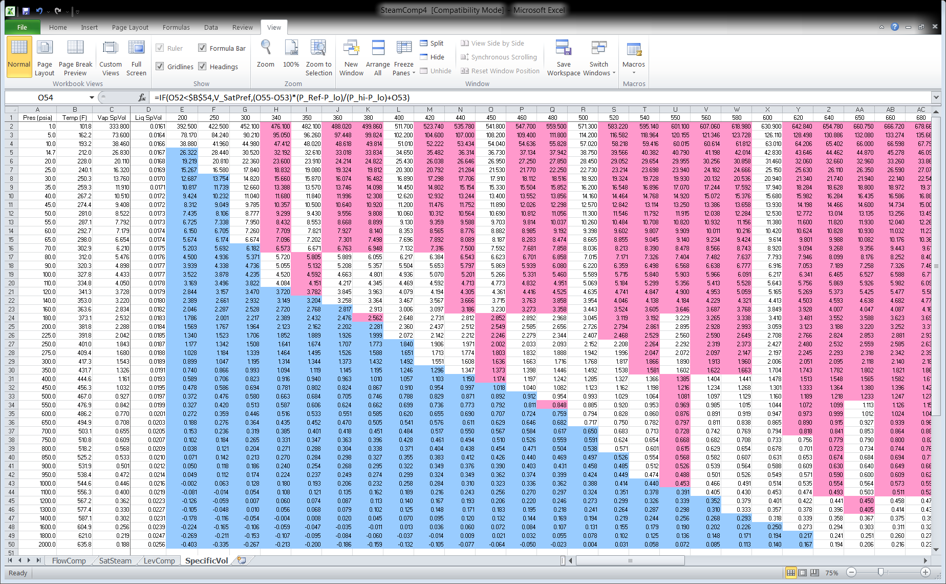
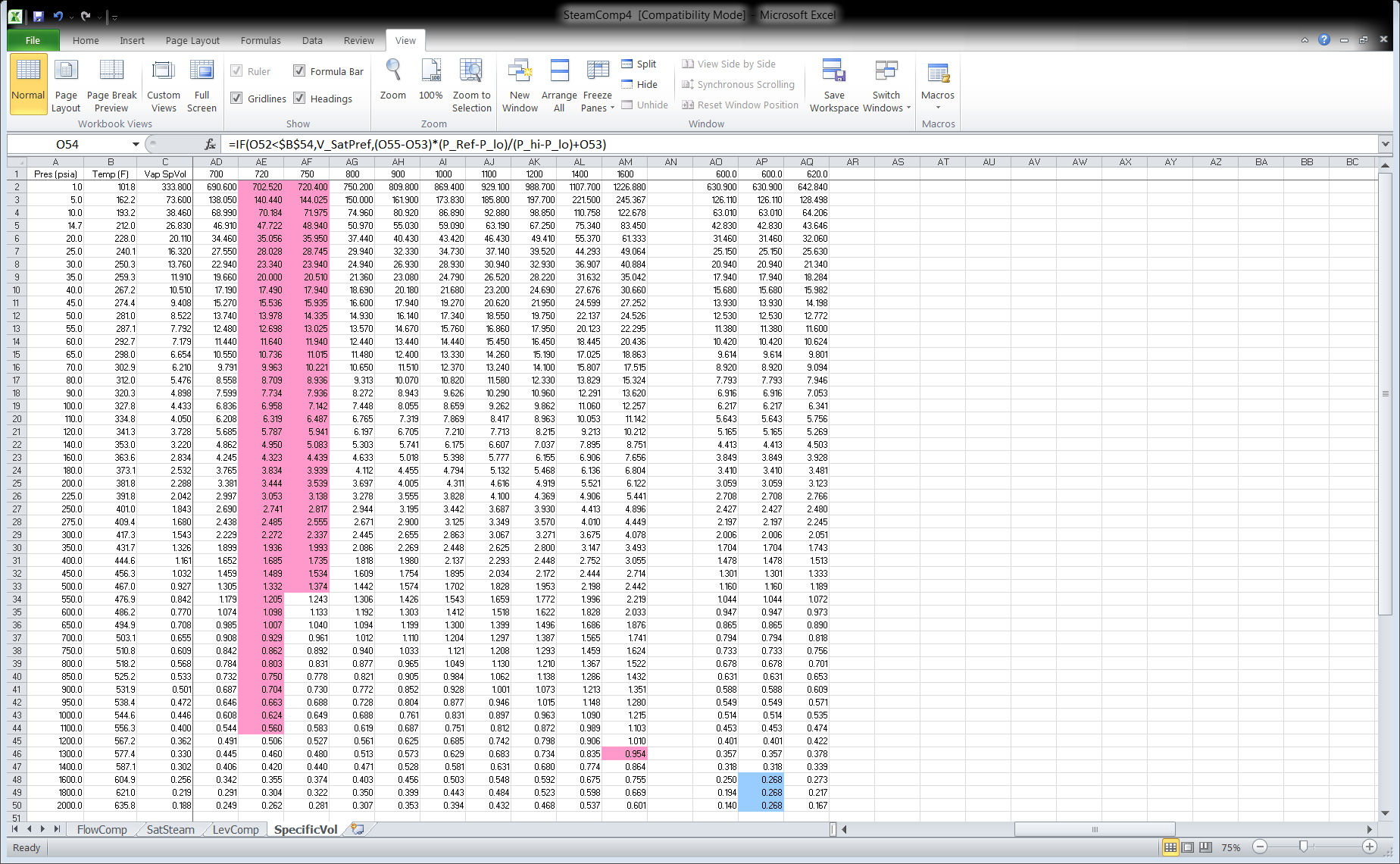
SAS has developed an Excel spreadsheet named SteamComp4 that provides the CHARC block entries given the design pressure and temperature and the maximum expected pressure and temperature. The spreadsheet has four tabs: FlowComp, SatSteam, LevComp, and SpecificVol. The tab FlowComp pertains to Superheated Steam (see Figure 2). Figures 3 and 4 show the table of steam specific volumes for varios pressures and temperatures. The blue cells indicate that liquid water is present and the magenta cells are interpolated values.
The user entry cells are highlighted in yellow. The X and Y columns are the calculated CHARC block entries. Contact SAS for more information.
Figure 2: Excel Spreadsheet SteamComp4 Tab FlowComp
Figure 3: Excel Spreadsheet SteamComp4 Tab SpecificVol (Page 1)
Figure 4: Excel Spreadsheet SteamComp4 Tab SpecificVol (Page 2)
Saturated Steam
Saturated Steam Flow Compensation
Saturated steam specific volume has only one degree of freedom. If pressure is specified, then temperature cannot be varied. Therefore, only the pressure compensation factor Comp_P is needed. The application is the same as for superheated steam except that CHARC block TY0003 is not needed and its input into CALCA block FY0001 should be locked at 1.0.
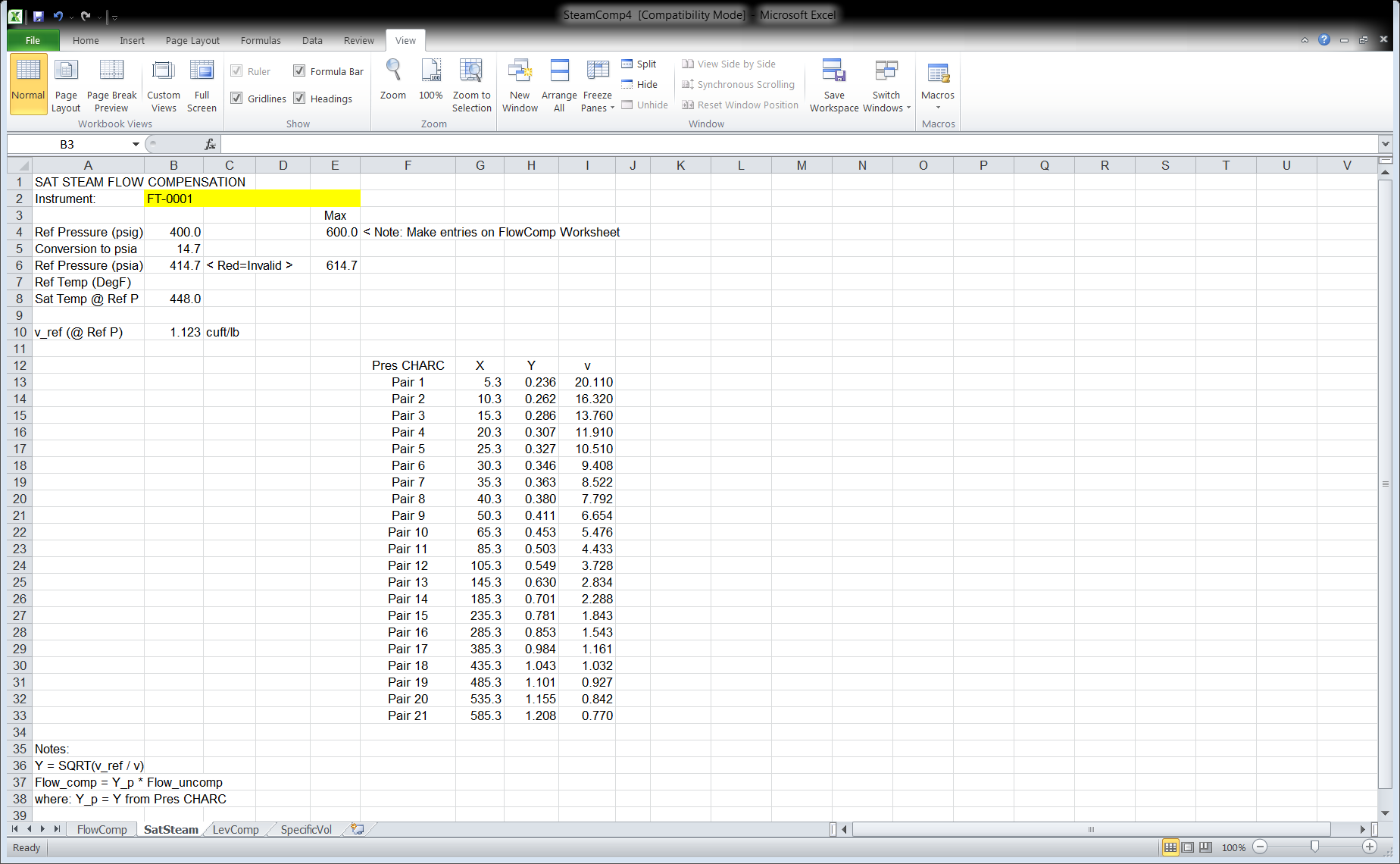
The Excel spreadsheet SteamComp4 has a tab named SatSteam, which is shown in Figure 5. The X and Y columns are the calculated CHARC block entries for the pressure compensation block PY0002. Please note that the design pressure and maximum pressure entries must be made on tab FlowComp. The temperature entries are ignored for saturated steam.


