
Crude oil typically contains significant quantities of organic sulfur compounds that, without sulfur removal, would end up in the resulting fuel products. If these fuels were burned, significant quantities of SO2 would be released into the atmosphere. Environmental regulations have been put in place to reduce these SO2 emissions, thus requiring refiners to remove the sulfur.
The major refinery process units involved in sulfur removal are hydro-desulfurization (HDS) and Sour Water Stripping (SWS). These units produce acid gas streams that cannot be vented to the atmosphere because their H2S content is dangerously high. Therefore, refineries include at least one, and often multiple, Sulfur Recovery Units (SRU) to convert the H2S in these acid gas streams to elemental sulfur.
The main objective of this post is to describe the process controls for a typical Sulfur Recovery Unit.
HDS Overview
The HDS process is used in many refineries to remove organic sulfur and nitrogen compounds from various process streams, such as reformer feed, kerosene, diesel, FCCU gasoil feed, and gasoline blending components. Hydrogen is combined with the feed and preheated by exchange with reactor effluent and by a fired heater. The vaporized mixture is charged to a reactor in which the organic sulfur and nitrogen compounds are converted to H2S and NH3 in the presence of a catalyst. The following reaction illustrates the conversion of methyl mercaptan, which is one of the simpler organic sulfur compounds:
CH3SH + H2 → CH4 + H2S (1)
The reactor effluent preheats the feed and is further cooled before entering a separator. The separator liquid is pumped to the product stripper. The separator gas stream becomes recycle gas containing H2S and hydrogen. The H2S is removed via absorption in a circulating amine stream followed by a stripper, where the H2S is released from the amine solution. The stripper offgas, which is commonly called amine acid gas (AAG), is primarily H2S and water vapor. The AAG is sent to the SRU to recover the sulfur.
The NH3 is removed by water-washing. The water is collected in a boot on the separator and sent to a Sour Water Stripper. Figure 1 is a greatly simplified process flow diagram of a typical HDS unit.

Figure 1: Typical HDS Process Flow Diagram
SWS Overview
Sour Water Strippers remove H2S and NH3 from sour water before the water is reused or discharged. The gas stream from the stripper overhead receiver, called sour water acid gas (SWAG), contains around 30-40% H2S and a similar amount of NH3, the rest being water vapor. The SWAG is sent to the SRU to recover the sulfur and destroy the NH3. Figure 2 is a greatly simplified process flow diagram of a typical Sour Water Stripper.

Figure 2: Typical Sour Water Stripper Process Flow Diagram
SRU Process Description
A typical SRU utilizes the Claus process to convert H2S in the two acid gas streams, AAG and SWAG, to elemental sulfur. The acid gas streams are partially combusted with air in the Combustion Chamber and Thermal Reactor, where a portion of the sulfur is formed.
The entire SWAG stream is sent to the Combustion Chamber along with a portion of the AAG. The AAG is needed in the Combustion Chamber because the SWAG’s low H2S content makes it more difficult to combust. The rest of the AAG bypasses the Combustion Chamber and enters the Thermal Reactor. The Thermal Reactor contains a Waste Heat Boiler to recover the heat of reaction as 600# steam.
The Combustion Chamber conditions are set to favor the conversion of NH3 to elemental nitrogen rather than to NOx. If NOx is generated, it will combine with any remaining NH3 to form ammonium nitrate. When cooled, the ammonium nitrate will condense to a solid and plug up the unit.
Liquid sulfur is condensed in the first Sulfur Condenser and the remaining reaction gases are reheated before entering the first converter. The converter utilizes a catalyst to continue the conversion to sulfur, which is condensed in the Sulfur Condenser. This process is repeated for Converters 2 and 3 until most of the sulfur is removed, leaving a tail gas stream that contains a small quantity of H2S and SO2. The tail gas is either incinerated or sent to a Tail Gas Unit (TGU) for further sulfur recovery. Figure 3 is a greatly simplified process flow diagram of a typical SRU.

Figure 3: Typical Sulfur Recovery Unit Process Flow Diagram
SRU Reactions
The following reaction occurs in the Combustion Chamber where the H2S in the acid gas is partially combusted to SO2:
2H2S + 3O2 → 2SO2 + 2H2O (2)
The Thermal Reactor and the Converters then perform the following reversible reaction to convert the H2S and SO2 to sulfur:
2H2S + SO2 ←→ 3S + 2H2O (3)
The maximum yield is obtained when the reactants are in the stoichiometric proportion of two moles H2S per mole of SO2 as shown in equation 3. Therefore, the combustion air that supplies the O2 in equation 2 must be exactly controlled to yield the proper amount of SO2 to satisfy the 2-to-1 mole ratio for equation 3.
Oxygen Enrichment
As equation 2 indicates, oxygen in the air is required for the reaction to proceed. However, 79% of the air contains inert components, such as nitrogen and argon. These components merely take up space in the unit. Replacing some of the air with pure oxygen allows a significant increase in unit capacity.
Process Control Overview
The main process control applications in a typical SRU are:
- Tail Gas Excess H2S Control
- Acid Gas Air Ratio Control
- Total Combustion Air Control
- Oxygen Injection Control
- Acid Gas Feed Controls
- Air Blower Controls
Tail Gas Excess H2S Control
The key indicator of proper combustion is the tail gas analyzer, which measures the H2S and SO2 content. It provides a calculated result indicating the amount of excess H2S in the tail gas:
Excess H2S = H2S – 2SO2 (4)
When the combustion is set exactly correct, the excess H2S is zero. If the excess H2S is positive, then more air must be added to convert the excess H2S to SO2. If the excess H2S is negative, then the air must be reduced to increase the H2S and decrease the SO2. The air rate adjustments are made by an analyzer controller that adjusts the combustion air controller setpoints, as shown in Figure 4.
When the output reaches a limit, the AAG or SWAG ratio must be adjusted to bring the output back into operating range. For example, if the output is at its high limit, then the AAG or SWAG ratio should be increased.
Acid Gas Air Ratio Control
The tail gas analyzer cannot indicate changes in acid gas rate immediately – a time lag always occurs. Therefore, feedforward control is incorporated to prevent acid gas rate changes from disturbing the combustion control.
Each acid gas stream requires a certain ratio of air per unit of acid gas flow for proper combustion. This ratio can be used to estimate the air rate needed for each acid gas. Figure 4 shows the two ratio controllers (X) in the combustion air control scheme.
Total Combustion Air Control
Combustion air control is performed by splitting the air into two streams. Each stream has its own flow controller. One stream, the trim air, has a smaller flow range and control valve than the other stream, which is referred to as main air. The dual air flow control scheme provides more precise control over the total air flow than a single flow controller.
The total combustion air controller backs out an equivalent rate of air to offset the oxygen injection rate. The oxygen rate is filtered to prevent a sudden change in air rate that might upset the blowers. The remaining air rate is obtained by adjusting the trim and main air flow controller setpoints.
Air flow changes are made preferentially to the trim air. However, when the trim air flow control valve gets outside of a reasonable operating range (e.g., 15 – 40%), air flow is automatically swapped between the trim air and the main air to bring the trim air back into control range. For example, if the trim air valve gets too far open, then the main air setpoint is increased and the trim air setpoint decreased by the same amount to shift air from the trim air to the main air.
In the event of an instrument problem, the operator can put either air flow controller into manual. All subsequent flow changes will now be made on the other flow controller, provided that it is in automatic / remote mode.
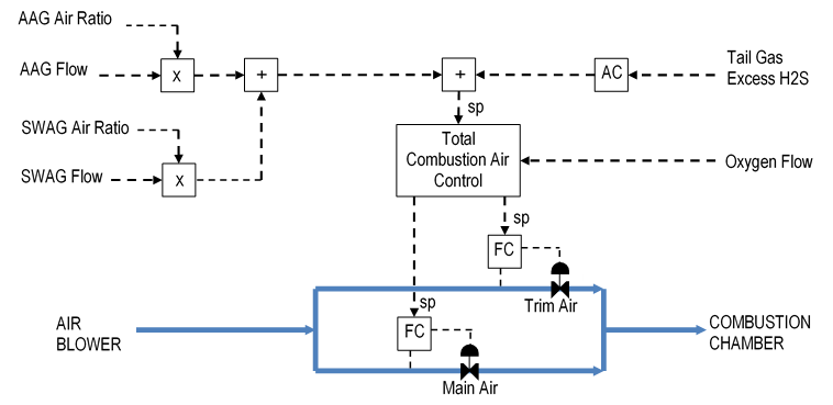
Figure 4: Typical SRU Combustion Air Controls
Oxygen Injection Controls
Oxygen injection can be controlled a number of different ways. In one of the simpler schemes, the operator enters the desired percent of oxygen in the combustion air and the controls adjust the oxygen flow. The percent oxygen can vary between 21 (air only) and 100 (oxygen only). Equation 5 shows the calculation for percent oxygen.
FractO2 = 100 * [0.21 * AirFlow + O2Flow] / [AirFlow + O2Flow] (5)
By re-arranging equation 5, we can directly calculate the oxygen flow required to meet the percent oxygen setpoint at the required equivalent air rate, as shown in equation 6. Figure 5 shows the control scheme.
O2Flow = [FractO2 – 0.21] / [3.762 * FractO2] * ReqdAir (6)

Figure 5: SRU Oxygen Injection Control
Oxygen Constrain Controls
The oxygen injection control scheme relies on the board operator to adjust the percent oxygen setpoint based on the need for acid gas throughput and the various constraints on oxygen. For example, SRUs are often limited to maximum percent oxygen due to metallurgical constraints. This constraint can be easily handled with a setpoint limit on the percent oxygen. A more difficult constraint to handle is maximum Combustion Chamber and Thermal Reactor temperatures to prevent refractory damage. As oxygen is increased, the flame temperature also increases.
Automatic constraint control can be implemented to deal with these constraints. It can monitor the need for oxygen, which is indicated by combustion air backpressure and/or air valve position, and adjust the oxygen percent based on the constraints. However, this level of complexity is seldom needed or desired.
Acid Gas Feed Control
The acid gas streams can be fed to the SRU on pressure control or, in the case of multiple SRUs, base loaded. Only one of the SRUs should be on pressure control at a time.
As described previously, the AAG must be split into two streams, one to the Combustion Chamber and the other to the Thermal Reactor. The pressure controller should cascade to the flow controller that manipulates the control valve to the Thermal Reactor, as shown in Figure 6.
The AAG flow to the Combustion Chamber should be on flow control and set in ratio to the total AAG flow. The ratio should be set to send one-third of the total AAG to the front burner to provide the conditions necessary to prevent NOx formation.

Figure 6: SRU Acid Gas Feed Controls
Air Blower Controls
An SRU typically has two air blowers to provide combustion air. Each blower is usually designed to provide 100% of the required air rate. Therefore, only one blower is needed in service. However, both blowers are often running to prevent an SRU shutdown due to blower failure. To ensure proper operation, the following blower controls are implemented:
- Anti-surge control – maintains the flow through the blower above the surge point by adjusting the blowoff control valve.
- Performance control – adjusts the blower speed or the suction valve to meet process demand for air, as measured by air header pressure.
- Load balance – adjusts the speed or suction valve to balance the loads, thus preventing one blower from blowing off considerably more than the other.
Figure 7 shows the controls for a turbine-driven blower and for a motor-driven blower.

Figure 7: SRU Air Blower Controls
Load Balance Objective
The header pressure controller in Figure 7 can control the pressure at any combination of governor and suction valve positions. For example, blower A governor could be near minimum speed while blower B suction valve is near wide open. The objective of Load Balance is to adjust the governor and suction valve positions to balance the loads on the blowers. This is done by manipulating the bias controllers shown in Figure 7.
When both blowers are blowing off, which will almost always be the case because each blower is sized to be 100% of design, then the Load Balance adjusts the loads based on their relative discharge pressures. The operator designates one of the blowers to be dominant and the other blower is set to have a slightly lower discharge pressure. This arrangement ensures that, should the dominant blower trip, the other blower can take over control before the air rate falls off significantly, thus avoiding a trip of the entire unit.
COPE Process
Gore, Allison and Associates (GAA) has developed the COPE process to greatly improve SRU operation. The COPE design includes an acid gas burner that can handle all of the acid gas, AAG and SWAG, and can completely destroy the NH3 in the SWAG. There is no longer a need to send a calculated portion of the AAG to the Combustion Chamber and bypass the remainder. An AAG pre-heater is added to prevent the AAG from condensing light components in the SWAG. Also, a recycle line provides a means of cooling the flame when oxygen is injected. Figure 8 shows the COPE modifications to the process.

Figure 8: COPE Process Flow Diagram
No.1 Condenser Recycle Gas
Oxygen injection is usually limited by high Thermal Reactor temperature. The COPE design includes the ability to reduce Thermal Reactor temperature by injecting steam into the COPE burner and also by recycling tail gas from the outlet of Condenser No.1 to the COPE burner.
An ejector is included in the design to pump the recycle gas from the No.1 Condenser to the burner. The ejector is driven by the same steam that is used to cool the burner. The steam rate is controlled separately so that the first cooling action is provided by steam alone. After the steam reaches a preset rate, recycle is brought in to increase the cooling. The steam and recycle flow rates are set by a characterizer that provides the required steam and recycle rate at various oxygen flow rates. The operator can adjust the steam and recycle gas flows up or down via a gain factor. Figure 9 shows the recycle gas control scheme.
