Introduction
The general purpose of petroleum refining is to produce useful products from crude oil. Crude is primarily a mixture of many hydrocarbon components that range from the lightest, methane, to the heaviest, asphalt. It also includes organic sulfur and nitrogen compounds as well as water and dissolved salts.
A typical refinery includes the following process units:
- Crude Unit
- Virgin Light Ends (VLE) Unit
- Naphtha Reformer
- Hydrocracking Unit (HCU)
- Fluid Catalytic Cracking Unit (FCCU)
- Cat Light Ends (CLE) Unit
- Hydro-desulfurization (HDS) Unit
- Alkylation Unit
- Coker
- Gasoline Blending
- Amine Treating and Sour Water Stripper
- Sulfur Recovery Unit (SRU)
- Utilities
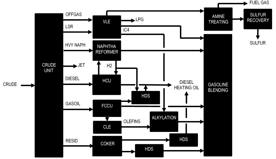
Figure 1 is a block diagram showing the typical process flow for a refinery. It should be noted that not all refineries have these same process units, that the process units may vary in design, and that the flows from unit to unit may also be considerably different.
Figure 1: Typical Refinery Block Diagram
Crude Unit
The Crude Unit usually has three distillation towers: Preflash, Atmospheric, and Vacuum. The Preflash tower removes light hydrocarbons from the crude before entering the Crude Heater and the Atmospheric tower. As the names imply, the Atmospheric tower operates at a pressure slightly above atmospheric and the Vacuum tower operates at a vacuum.
The Atmospheric tower produces the following product streams:
- Offgas to VLE (combined with Preflash overhead)
- Light straight-run (LSR) naphtha to VLE
- Heavy naphtha sidedraw to reforming
- Kerosene sidedraw to jet fuel (may go to HDS first)
- Diesel (also called distillate) sidedraw to HCU
- Atmospheric gasoil (AGO) to FCCU
- Reduced crude to Vacuum tower
The Vacuum tower produces the following product streams:
- Light vacuum gasoil (LVGO) sidedraw to FCCU
- Heavy vacuum gasoil (HVGO) sidedraw to FCCU
- Vacuum resid to Coker.
The composition of these streams must be controlled to prevent operating problems in the downstream units. For example, heavy naphtha must not contain long-chain hydrocarbons that would produce excessive coke formation in the reformer unit. Kerosene typically becomes jet fuel which must not contain heavy components or water that can freeze at high altitude.
The simpler refineries have a Flash Drum instead of a Preflash tower, and no Vacuum tower. The Atmospheric tower is also called a Crude Tower in some refineries.
Virgin Light Ends Unit (VLE)
The VLE unit separates the gas and light liquid hydrocarbons from the Crude Unit into the following product streams:
- Fuel gas to Amine Treating
- Propane (C3) to LPG product
- Mixed butanes to Alkylation
- Stabilized light naphtha to Gasoline Blending
The VLE usually has the following separation equipment:
- Absorber to remove C3 and heavier from the fuel gas by lean oil absorption
- Sponge Absorber to remove lean oil carryover from the Absorber
- Stripper to remove ethane and lighter from the Absorber bottoms stream
- Depropanizer to remove propane from the Stripper bottoms product
- Debutanizer to remove mixed butanes from the Depropanizer bottoms
The VLE is also called a Saturated Gas Plant (or Sats Gas) in some refineries. The term VRU for vapor recovery unit is also used.
Naphtha Reformer
Heavy naphtha from the Crude Unit and HCU is sent to the Naphtha Reformer to increase its octane before becoming gasoline. Octane is a measure of how smoothly fuel burns. If the octane is too low, the fuel will burn erratically and cause knocking, which can damage the engine. Straight-chain hydrocarbons have very low octane, whereas branched-chain hydrocarbons and aromatics have high octane.
The feed must usually be hydrotreated to remove sulfur and nitrogen compounds, which are reformer catalyst poisons. The catalyst promotes isomerization of straight-chain hydrocarbon compounds to branched isomers, dehydrocyclization of hydro-carbon compounds to aromatics, and hydrocracking of long-chain hydrocarbons into shorter-chain compounds. One of the major byproducts of naphtha reforming is hydrogen that is needed in the HCU and HDS units.
Reformers are classified into the following types:
- Semi-regen having typically 4 reactors with interheating between reactors.
- Cyclic having 4 reactors plus a swing reactor that can be put into the place of any of the other four.
- Continuous Catalyst Regeneration (CCR) in which the catalyst moves from one reactor section to the next and then into a regeneration tower.
The Semi-regen unit must be completely shut down for catalyst regeneration every couple of years. The Cyclic unit performs regeneration somewhat continuously via the swing reactor, but relies on a very complicated header system with large block and bleed valves to keep the regeneration air separated from the hydrocarbons. The CCR unit has become popular with refiners because it is a truly continuous process.
Other names for a naphtha reformer are Powerformer and Ultraformer, which are trade names for the licensed process.
Hydrocracking Unit (HCU)
The diesel sidedraw from the Crude Unit is usually sent to the HCU to crack the heavier hydrocarbon compounds into lighter gasoline and heating oil components. Some units also crack gasoil. Hydrogen from the reformer is consumed in the HCU to saturate the cracked compounds. The process also removes sulfur and nitrogen from the liquid products.
The following product streams, listed from lightest to heaviest, are produced:
- Hydrogen purge to fuel gas
- Light hydrocarbon vapor to fuel gas
- Butane product
- Light naphtha to gasoline blending
- Heavy naphtha to reformer feed
- Distillate to jet and/or diesel
- Unconverted oil to FCCU feed or storage.
Some refineries call their HCU a Unicracker, which is a licensed trade name.
Fluid Catalytic Cracking Unit (FCCU)
The overall process objective of the Fluid Catalytic Cracking Unit (FCCU) is to crack gasoil to produce lighter hydrocarbon products. The following product streams, listed from lightest to heaviest, are produced:
- Offgas to Cat Light Ends
- Cat naphtha to Cat Light Ends
- Light cycle oil (LCO) to heating oil
- Heavy cycle oil (HCO) which is usually recycled back to the feed
- Slurry which is blended to fuel oil but can also be recycled back to the feed
An alumina-silica catalyst is used to promote the more desirable cracking reactions over those typical of purely thermal cracking. Coke forms on the catalyst as the reactions proceed, eventually deactivating the catalyst. Therefore, the catalyst must be periodically regenerated by burning off the coke.
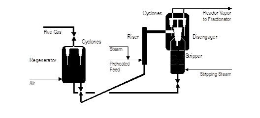
To make this process continuous, the catalyst is made of finely-divided particles that are readily fluidized. Fluidization allows the coke-laden (spent) catalyst to gravity-flow from the reaction vessel to a regenerator vessel, where the coke is burned off. Regenerated catalyst then flows back to the reaction vessel via a small pressure difference between the two vessels. Figure 2 is a sketch of the process flow for a typical FCCU Reactor and Regenerator.
The vapor from the reactor flows to the Main Fractionator, which is similar to a Crude Tower. Part of the vapor is condensed by pumparounds and in overhead condensers. Cat naphtha is drawn from the overhead accumulator and the remainder of the condensate is refluxed to the tower. LCO and HCO products are sidedraw streams. The slurry comes from the bottom of the fractionator.
The key process variable is the reactor temperature. It determines the conversion, which is the percentage of gasoline and lighter components in the final slate of products, plus the coke produced (i.e., all products except LCO and slurry). Conversion indicates the severity of the cracking reaction.
Figure 2: Typical FCCU Reactor / Regenerator
Cat Light Ends Unit
The CLE unit separates the gas and light liquid hydrocarbons from the FCCU into the following product streams:
- Fuel gas to Amine Treating
- Propane/Propylene (P-P) to Alkylation
- Butanes/Butylenes (B-B) to Alkylation
- Stabilized cat naphtha to Gasoline Blending
The CLE unit usually has the following separation equipment:
- Absorber to remove P-P and heavier from the fuel gas by lean oil absorption
- Sponge Absorber to remove lean oil carryover from the Absorber
- Stripper to remove ethane/ethylene and lighter from the Absorber bottoms stream
- Depropanizer to remove P-P from the Stripper bottoms product
- Debutanizer to remove B-B from the Depropanizer bottoms
Many CLE units have the Debutanizer immediately following the Stripper in the process flow. The Debutanizer overhead stream is sent to a Splitter that splits the feed into P-P overhead product and B-B bottoms product.
The CLE is also called a VRU (vapor recovery unit) in some refineries.
Hydro-Desulfurization Unit (HDS)
The HDS process is used extensively in a refinery to remove organic sulfur and nitrogen compounds from various process streams, such as reformer feed, kerosene, diesel, FCCU gasoil feed, and gasoline blending components. Hydrogen from the Reformer is combined with the feed and preheated by exchange with reactor effluent and by a fired heater. The vaporized mixture is charged to a reactor in which the organic sulfur and nitrogen compounds are converted to H2S and NH3 in the presence of a catalyst. The H2S is removed from the product via absorption in a circulating amine stream. The NH3 is removed by water-washing.
Alkylation Unit
The overall objective of an Alkylation Unit is to produce a high-octane gasoline blending component called alkylate by reacting propylene and butylenes from the CLE unit with iC4 from the VLE unit. The reaction requires a large recycle of iC4 to suppress undesirable side reactions.
The reaction also requires either sulfuric acid or hydrofluoric (HF) acid as a catalyst. The advantage of HF acid is that the reaction occurs at cooling water temperature, whereas the sulfuric acid process requires refrigeration to achieve the proper reaction temperature. However, HF is extremely dangerous and difficult to contain because it is highly corrosive.
Coker
The Coker thermally cracks the Vacuum Tower resid to obtain gasoline and heating oil products while also producing petroleum coke that can be used as electrodes in the aluminum process. The Delayed Coking process is the most widely used. A Fluid Coking process was developed but it produced inferior coke that could only be used as fuel.
The term “delayed” refers to the heated resid entering a large drum in which the stream is slowed down thus allowing the coke to form on the walls. When the drum is nearly full, it is taken off-line and the coke cut out of the drum. The feed is switched to a second drum during the coke cutting. The vapor from the in-service coke drum enters a fractionator that is similar to the FCCU Main Fractionator.
Gasoline Blending
The gasoline product streams from the process units discussed above are blended to produce the various grades of finished gasoline. Key blending targets are octane index and vapor pressure. Each grade has a target octane index, which is a mathematical combination of the Research Octane Number (RON) and the Motor Octane Number (MON). RON measures the knocking that an engine exhibits while accelerating, whereas MON measures the knocking while at constant speed.
Vapor pressure determines how easily an engine starts in cold or hot weather. Cold weather requires a higher vapor pressure. However, a high vapor pressure gasoline in hot weather may vapor-lock the engine. Therefore, the vapor pressure specification varies according to the season of the year.
Gasoline is in-line blended, which means that each component stream is pumped into a header on flow control. The flow setpoints are automatically adjusted to achieve the desired properties as well as the total flow of product. Both vapor pressure and octane are continuously analyzed to provide immediate feedback to the blending controls.
Amine Treating and Sour Water Stripper
Various amine solutions, such as mono-ethanolamine (MEA) and di-ethanolamine (DEA), are used to remove H2S from fuel gas streams. The amine solution absorbs H2S and is then heated in a regeneration tower to release the H2S into an acid gas stream. The acid gas, called amine acid gas (AAG), is sent to a Sulfur Recovery Unit (SRU) for conversion to elemental sulfur.
Some amine treating units are self-contained and some are sections of the larger process units described above. For example, the HCU and HDS units each have an amine treating section.
Water is used to scrub various gas streams of H2S and ammonia (NH3). These streams then become sour water and require processing before they can be reused. In a Sour Water Stripper, the sour water feed is heated and sent to a reboiled stripping tower where H2S and NH3 are removed from the water and sent to a Sulfur Recovery Unit as sour water acid gas, or SWAG.
Sulfur Recovery Unit
The Sulfur Recovery Unit (SRU) converts H2S in the AAG and SWAG streams into elemental sulfur via both thermal and catalytic conversion. The NH3 in the SWAG is disassociated into elemental nitrogen.
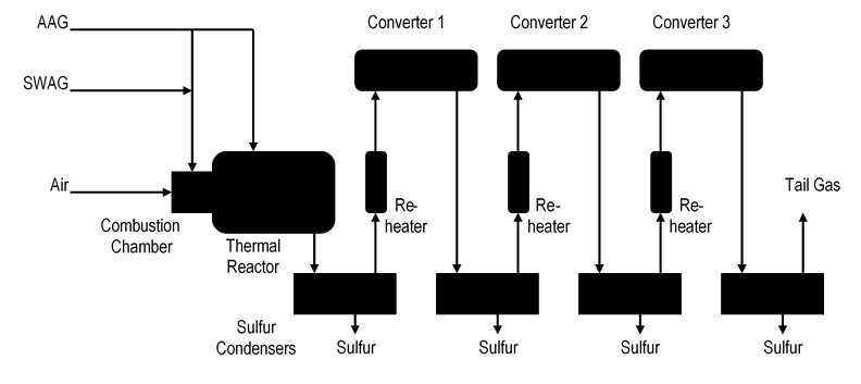
The acid gas streams are partially combusted with air in the Combustion Chamber and Thermal Reactor, where a portion of the sulfur is formed. The Thermal Reactor contains a Waste Heat Boiler to recover the heat of reaction as 600# steam. Liquid sulfur is condensed in the first Sulfur Condenser and the remaining reaction gases are reheated before entering the first converter. The converter utilizes a catalyst to continue the conversion to sulfur, which is condensed in the next Sulfur Condenser. This process is repeated for Converters 2 and 3 until most of the sulfur is removed, leaving a tail gas stream that contains a small quantity of H2S and SO2. The tail gas is either incinerated or sent to a Tail Gas Unit (TGU) for further sulfur recovery. Figure 3 is a simplified schematic of a typical SRU process.
The maximum sulfur yield is obtained when the reactants are in the stoichiometric proportion of two moles H2S per mole of SO2. The air that supplies the O2 for partial combustion must be exactly controlled to yield the proper amount of SO2 to satisfy the desired 2-to-1 mole ratio.
Pure oxygen is sometimes used to supplement the air, especially in units that are hydraulically limited. Air contains 79% inert components, such as nitrogen and argon, which take up space in the unit. Replacing some of the air with pure oxygen allows a significant increase in unit capacity.
Figure 3: Typical Sulfur Recovery Unit
Utilities
The following utilities are required for a typical refinery:
- Fuel gas
- Boiler Feed Water (BFW) treating
- Steam generation (various pressures)
- Utility and instrument air
- Waste water treating
- Flare systems
Fuel gas from the various process units described above is collected in a mixing drum and natural gas is added when the fuel demand exceeds supply. Liquid butane can also be used to supplement fuel gas.
Water is filtered and treated to provide BFW for steam generation. A refinery usually has multiple parallel boilers to produce 600# steam for driving turbines. The 600# steam is let down to lower pressures, such as 150# and 50#, to provide heat for reboilers and stripping steam for removing light hydrocarbons from product streams.
Control valves require instrument air to operate. Multiple air compressors are employed to provide the instrument air as well as utility air (sometimes called plant air). The air must be dried to prevent moisture buildup and water crystal formation during cold weather.
Waste water streams must be treated to remove oil and other contaminants before discharging into the environment. A flare system collects all of the hydrocarbon gas discharged from the various process units, knocks out liquids, and burns the resulting gas using atomizing steam to provide complete combustion.


