
Introduction
Fired heaters are used extensively in the refining and petrochemical industries for heating hydrocarbon streams. Typical fired heater services are crude vaporization, reactor feed preheat, and reboiler heat input for distillation towers.
To maximize heat transfer, the hydrocarbon charge is usually split into separate passes before entering the heater. The pass flows must be carefully controlled to prevent the hydrocarbon charge from coking the tubes. Normally, a flow controller is installed for each pass to provide the desired control. These pass flow controllers together also set the total charge to the heater.
How should the pass flows be split to minimize coking? The simplest approach is to set the flows equal. This solution is valid provided that the heat transfer for each pass is uniform, thus evenly heating the charge. However, the heat transfer is usually not uniform for various reasons, the most obvious being variations in the flame pattern. The charge would be overheated in the hotter passes and underheated in the colder passes.
The best way to ensure even heating of the charge is to adjust the flow split such that the pass outlet temperatures are balanced. Therefore, the passes having the higher heat transfer receive more charge, thus preventing over¬heating and possible coking of the heater tubes.
Pass Balance Application
Strategic Automation Services (SAS) has developed the Pass Outlet Temperature Balance application to automatically balance a heater’s pass outlet temperatures. Figure 1 shows a typical application for a six-pass heater. The application can handle a maximum of eight passes.
The application includes a controller that adjusts the pass flow controller (FC) setpoints based upon the heater inlet temperature (TI) and the pass outlet temperatures (TI). The controller also controls the total flow through the passes using the sum of the flows.
Control Objectives
The Heater Pass Balance application adjusts up to eight heater pass flows to satisfy both of the following control objectives:
- maintain an operator-entered total charge flow setpoint;
- balance the pass outlet temperatures.
These objectives are discussed in detail in the following sections.

Figure 1: Typical Heater Pass Balance Application
Control Objective – Total Charge Control
Total charge control adjusts each pass flow by the same amount in the same direction, thus altering the total flow rate without changing the flow distribution. The amount and direction are based upon the current deviation of the total flow from its setpoint. The amount is also limited to a maximum ramp rate so that the total flow setpoint is achieved in a smooth transition. The ramp rate for flow increases can be set to a different value than the ramp rate for flow decreases.
For example, if the total charge is below setpoint by 300 BPD for a six-pass heater, then the application calculates that each pass flow must be increased by 50 BPD. If the ramp rate for flow increases is less than this amount, then the increases will be limited to the ramp rate.
Control Objective – Pass Balance
Pass balance control shifts the pass flows to balance the outlet temperatures without changing the total flow rate. For example, a pass flow is increased versus the others when its corresponding outlet temperature is above the average outlet temperature. Likewise, a pass flow is decreased versus the others when its corresponding outlet temperature is below the average outlet (see Table 1).
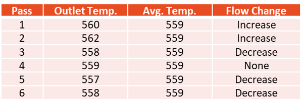
Table 1: Pass Balance Control Action Example
Pass Balance Algorithm Details
The pass balance control algorithm uses a model of the heat transfer in the pass to calculate the flow change. The model is the sensible heat equation, which can also be applied to vaporization of a wide-boiling-range hydrocarbon such as crude oil:
Q = Cp * Flow * (Tout – Tin) (1)
The control algorithm assumes that the heat absorbed by the pass is independent of the flow rate and the outlet temperature over a limited range. Therefore, the flow change required to balance the pass outlet temperature with the other passes can be calculated as follows:
ΔFpass(i) = Kpb * Fpass(i) * [Tout(i) – Tavg] / [Tavg – Tin] (2)
where:
ΔFpass(i) = Required flow change for pass i;
Kpb = Tuning factor for pass balance control;
Fpass(i) = Flow through pass i;
Tout(i) = Pass i outlet temperature;
Tin = Heater inlet temperature;
Tavg = Average outlet temperature.
The average outlet temperature Tavg is the target to which all passes are attempting to balance. It is obtained by calculating the flow-weighted average of the pass outlet temperatures:
Tavg = Σ [Fpass(i) * Tout(i)] / Σ Fpass(i) (3)
The summations are performed for the number of heater passes.
Benefits
The Heater Pass Balance application ensures that all pass outlets are at the lowest possible temperature for the current operation. Therefore, coking in the tubes is minimized and heat transfer efficiency is greater. In addition, the total flow ramping ability ensures a smooth transition during major charge rate changes.
Control Features
The Heater Pass Balance application includes several features that modify the normal control action. These features limit the application to a reasonable operating range and/or prevent it from taking overly-aggressive control action. The following sections discuss each of the features.
Pass Flow Controller Setpoint Limits
The application will not violate the setpoint limits on the pass flow controllers. Therefore, the engineer can protect the pass flows from approaching the heater low-flow shutdown trips by setting the low setpoint limits on the pass flow controllers.
When a pass flow reaches its setpoint limit, the overall control action continues with the non-limited passes. However, at least one of the pass outlet temperatures will deviate from the others in this case.
Saturated Pass Flow Control Valve
A saturated pass flow control valve can severely limit the effectiveness of this application. The term “saturated” means that the valve is wide open, or at its high output limit. If the outlet temperature of the saturated pass increases above the average temperature, it cannot be brought back to the average because additional flow cannot be sent through the pass. Therefore, control is lost over this pass and its outlet temperature could continue to rise.
When the saturated pass outlet temperature is above the average outlet temperature, the application excludes the saturated pass from the average outlet temperature calculation and from subsequent control action. The unsaturated pass outlet temperatures are then balanced at the new average.
When the saturated pass outlet temperature is below the average outlet temperature, then this pass is included in the average temperature calculation. In this case, the desired control action is to reduce the flow, which the application can accomplish because the control valve is free to close.
Maximum Pass Flow Deviation
This application includes a limit on how far the pass flows can deviate from each other. The deviation is defined as the flow difference between the highest and lowest pass flows. If the current pass flow deviation exceeds this limit, the application suspends all control action that would make the deviation worse. However, the application does take control action that reduces the deviation.
This feature is included to alert the operator to a severe imbalance in the heater firing. The application is reacting to the imbalance by forcing more and more flow through the passes that are receiving the most heat transfer. When the maximum pass flow deviation limit is reached, the operator should investigate the situation.
Maximum Pass Flow Change
The application is prevented from making large pass flow changes by limiting the pass balance control action to a maximum pass flow change. When the largest pass flow change is greater than the maximum allowed, then all pass flow changes are scaled such that the largest is equal to the maximum. This feature provides a smoother approach to balanced temperatures than if the entire calculated flow change were implemented at once.
Control Frequency
The timing of the control action can be set differently for pass balance control versus total charge control. This is necessary because the response times are markedly different. Pass balance action requires a response on the outlet temperature after a change in the pass flow. This can take anywhere from 5 to 10 minutes due to the inherent thermal lag in the heater. However, the total charge control response is much quicker, usually 5 to 10 seconds. Therefore, total charge control action is implemented at a higher frequency than pass balance control action.
Heater Passes Out-of-Service
The control engineer can designate individual passes to be out-of-service in the event that they have instrumentation problems. When the application is turned on, their corresponding flow controllers will remain in MAN and they will not be included in the control action. At least two passes must be designated to be in-service.
Pass Flow Controller in MAN
If any in-service pass flow controller is put into MAN, pass balance control goes into a hold state to prevent the possibility of overheating the pass. Pass balance control resumes when the pass flow controller is put back into AUTO. The total charge control continues functioning as long as at least one pass flow controller is in AUTO.
Bad Input
This application continuously checks all of its inputs for BAD status. If a temperature input becomes BAD, pass balance control goes into a hold state until the input becomes good again. Total charge control is allowed to remain on control because it is not affected by a bad temperature input.
However, if a flow input becomes BAD, both total charge control and pass balance control go into a hold state until the input becomes good again.
Application Shutdown
The entire Heater Pass Balance application will automatically turn itself off when it detects a system error, user error, or a configuration error. These conditions are extremely unusual and must be corrected by the control engineer.