Introduction
Fired heaters are used extensively in the refining and petrochemical industries for heating hydrocarbon streams. Typical fired heater services are crude vaporization, reactor feed preheat, and reboiler heat input for distillation towers.
The main purpose of each heater is to provide heat input to a process stream. The heat is provided by combusting fuel gas in a fire box. The process stream flows through metal tubes inside the fire box, absorbing heat through the tube walls. The combined tube outlet temperature indicates how much heat has been absorbed.
Combustion air is provided by a forced-draft (FD) fan and controlled by a flow controller that typically manipulates the FD fan damper. The optimum air rate is one which is just sufficient to provide complete combustion. At this condition, the slightest negative deviation in the air rate can cause a significant increase in carbon monoxide and/or unburned hydrocarbons. Larger deviations can even result in an explosive mixture.
The solution to controlling combustion this close to optimum is a cross-limiting control scheme in which the air rate leads the fuel gas on a demand increase, and lags the fuel gas on a demand decrease. This scheme ensures that the air is never deficient during load changes.
Figure 1 is a schematic of the overall combustion controls. The right-hand portion of the schematic shows the fuel cascade and the left-hand portion shows the air cascade. These two cascades are discussed separately below.
 Figure 1: Cross-Limiting Combustion Controls
Fuel Cascade
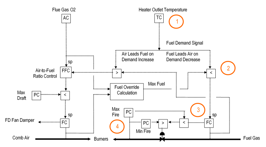
Figure 2 is the same schematic as Figure 1 except that numbered orange circles have been added to highlight the following items in the fuel cascade:
- Combined outlet temperature controller.
- Combustion air override.
- Fuel gas flow controller.
- Fuel gas header pressure override.
 Figure 2: Cross-Limiting Combustion Controls – Fuel Cascade
Fuel Cascade – Outlet Temperature Controller
The heater outlet temperature controller adjusts its output to maintain the operator-entered setpoint. The output is the fuel demand signal to the combustion controls.
The temperature controller is locked into automatic and local. The only way that the operator can stop the controller from manipulating the fuel gas is to put the fuel gas flow controller into local or manual. This will cause the outlet temperature controller output to track the fuel gas flow.
The setpoint does not initialize when the controller is tracking. The controller is configured to prevent bumping its output when the setpoint is changed and when the controller comes out of tracking.
Fuel Cascade – Combustion Air Override
The fuel demand signal from the outlet temperature controller goes to a low signal selector that overrides the demand signal when the combustion air is insufficient at the required air-to-fuel ratio. The second input to the low selector comes from a calculation of the maximum fuel rate allowed at the current air rate. This input overrides the fuel demand signal only when the combustion air flow controller has a significant low deviation (i.e., air flow below setpoint).
For example, assume that the outlet temperature controller is calling for a fuel increase. The fuel will not actually increase at first because the maximum fuel rate signal to the low selector holds it back. When the air rate finally does increase, then the maximum fuel rate signal increases which then allows the fuel to increase.
Fuel Cascade – Fuel Gas Flow Controller
The fuel override low selector output is connected to the fuel gas flow controller remote setpoint. The fuel gas flow controller output usually sets the fuel gas valve position, except when it is overridden by the burner pressure override (discussed next).
The fuel gas flow controller is normally in automatic and remote, but the operator can put the controller into local or manual to break the cascade to the combined outlet temperature controller. When the controller is in automatic and local, the operator can enter a setpoint. However, the setpoint initializes to the measurement when the controller is in manual.
Fuel Cascade – Fuel Gas Header Pressure Override
The fuel gas flow controller output to the fuel gas valve can be overridden when the burner pressure is above the maximum (max fire) or below the minimum (min fire). The controls include a separate pressure controller for each override along with a low selector for the max fire override and a high selector for the min fire override.
The pressure override controllers are locked into automatic. The setpoints are set just inside the trip settings to prevent the combustion controls from causing a trip. This means that the fuel gas flow controller is free to operate only between these two burner pressures. When the burner pressure approaches either of the limits, then the corresponding override controller begins to take over control via the signal selectors.
The low pressure override is somewhat risky because an instrument failure may cause the heater to over-fire. This risk should be eliminated by installing an additional pressure transmitter and using a high selector to pick the higher of the inputs.
Air Cascade
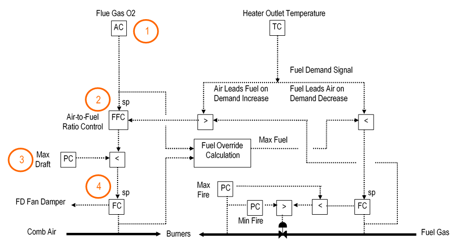
Figure 3 is the same schematic as Figure 1 except that numbered orange circles have been added to highlight the following items in the air cascade:
- Flue gas oxygen controller.
- Air-to-fuel ratio controller.
- Maximum draft override.
- Combustion air flow controller.
Figure 3: Cross-Limiting Combustion Controls – Air Cascade
Air Cascade – Flue Gas Oxygen Controller
If multiple flue gas oxygen analyzers are available, the flue gas oxygen controller automatically selects the lowest oxygen analyzer reading as its input. The controller output is the demanded air-to-fuel ratio.
The flue gas oxygen controller is locked into automatic and local. When the cascade to the combustion air is broken, the flue gas oxygen controller output tracks the air-to-fuel ratio.
The operator can enter a setpoint (for example 3%). The setpoint does not initialize when the controller is tracking. The controller is configured to prevent bumping its output when the setpoint is changed and when the controller comes out of tracking.
Air Cascade – Air-to-Fuel Ratio Controller
The output of the oxygen controller sets the setpoint of the air-to-fuel ratio controller. The air-to-fuel ratio controller output is the required combustion air rate.
The input to the ratio controller comes from another high selector. This selector picks either the fuel demand signal from the outlet temperature controller or the current fuel gas flow rate, whichever is higher. This selector allows the air to increase on a demand increase before the fuel is allowed to increase. On a demand decrease, the air is prevented from decreasing until the fuel rate decreases.
For example, assume that the temperature controller is calling for a fuel decrease. The air will not actually decrease at first because the current fuel gas rate signal to the high selector holds it back. When the fuel rate finally does decrease, then the air is allowed to decrease.
The air-to-fuel ratio controller is locked into automatic. It is normally in remote, but the operator can put this controller into local and adjust its ratio setpoint. The setpoint initializes to the current air-to-fuel ratio when the cascade to the air flow controller is broken.
Air Cascade – Maximum Draft Override
The air-to-fuel ratio controller output to the combustion air flow controller setpoint can be overridden when the heater draft is above the maximum. This override should be implemented only if the draft signal is reliable.
The draft override controller is locked into automatic. The setpoint is set just below the trip setting to prevent the combustion controls from causing a trip. When the draft approaches the setpoint, then the draft override controller begins to take over control via the low signal selector.
For example, assume that the air-to-fuel ratio controller output is increasing and as a result the draft is also increasing. The draft override controller output will now be decreasing as the draft approaches the setpoint and will eventually take over control of the air.
Air Cascade – Combustion Air Flow Controller
The draft override low selector output is connected to the combustion air flow controller remote setpoint. The combustion air flow controller output adjusts the FD fan damper.
The combustion air flow controller is normally in automatic and remote, but the operator can put the controller into manual to break the cascade to the air-to-fuel ratio controller. The setpoint initializes to the measurement when the controller is in manual.
Burner Management System Interface
The Burner Management System (BMS) monitors each heater and shuts down the heater when unsafe conditions are detected. The BMS also assists the operator in starting up the heater. The combustion controls are designed to work with the BMS by setting the fuel and air outputs to the positions that the BMS requires.
The BMS typically issues the following signals to the fuel controls:
- Fuel trip – put fuel flow controller in manual and close fuel valve.
- Main burner lightoff – open fuel gas valve to lightoff position.
- Release to modulate– allow fuel flow controller to be put into automatic.
The BMS typically issues the following signals to the combustion air controls:
- Air trip – put air flow controller in manual and close FD fan damper.
- Purge – open FD fan damper to purge position.
- Pilot lightoff – open FD fan damper to lightoff position.
- Release to modulate– allow combustion air flow controller to be put into automatic.

