Process control can be thought of as a hierarchy of controllers, with the simplest controllers at the bottom tier of the control system and the more complicated controllers at the higher tiers. Generally, the higher-tier controllers adjust the setpoints of the lower tier controllers, similarly to a cascade control structure.
The bottom tier of control is often referred to as Basic Regulatory Control (BRC). BRC consists of simple PID feedback controllers each having a single input and a single output (SISO). BRC keeps the process within equipment and safety limits and, in the absence of disturbances, keeps the key control variables reasonably close to setpoint.
The next tier of the control hierarchy is usually called Advanced Regulatory Control (ARC). ARC controllers typically have multiple inputs but only a single output (MISO) and utilize one or more of the following advanced control techniques:
- Feedforward control to better handle disturbances caused by external process inputs, such as feed rate.
- Decoupling to offset disturbances caused by the control action of other controllers.
- More sophisticated control algorithms, such as model-predictive control to handle difficult dynamics.
The next tier is often called Advanced Process Control (APC). The APC tier usually features Multivariable Control (MVC), such as Aspen Tech’s DMCplus. APC controllers usually have multiple inputs and multiple outputs (MIMO) and adjust the setpoints of either ARC controllers or BRC controllers.
The purpose of this document is to describe feedforward control, one of the more useful ARC techniques.
Background
Feedforward control pre-adjusts a manipulated variable (MV) when a change is detected in one or more disturbance variables (DV). If the feedforward action is well-tuned, the controlled variable (CV) is scarcely affected by the disturbance. Tuning involves correctly estimating the following:
- Feedforward gain, which is the overall change in the MV required for a unit change in the DV.
- Feedforward dynamic compensation, which is the path over time that the MV must follow to prevent a deviation in the CV from its setpoint (SP).
Feedforward Theory
Incremental Feedforward Control
Feedforward control should be implemented incrementally. The DV should be dynamically compensated and the change in the DV multiplied by the gain. The result is the incremental MV that is added to the current MV.
The incremental approach has the following advantages:
- Feedforward control can be turned on and off without bumping the output.
- Feedforward control action can be limited to a reasonable range, thus preventing spurious inputs from greatly affecting the application.
- The feedforward gain can be changed while the control is in service, because the new gain applies only to future changes in the DV.
Dynamic Compensation
Dynamic compensation is provided by the lead-lag algorithm, which characterizes the dynamics via a first-order lag and lead. The lead is like derivative in that it can make a very sudden change in the output whenever the input changes, depending on the value of the lead parameter. Therefore, lead is seldom used.
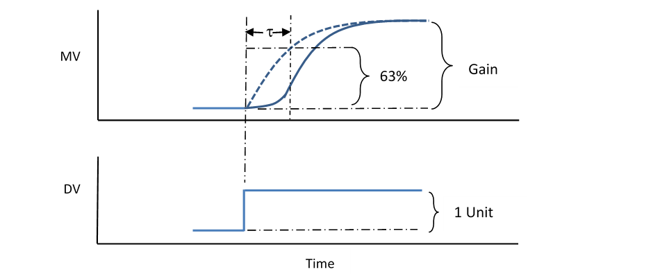
The solid blue line in Figure 1 shows the typical second-order lag response required for an MV due to a step change in a DV. The MV must be moved as shown to prevent the CV from deviating significantly. Typically, the response is simplified to a first-order lag, which is the blue dashed line in Figure 1. Notice that the first-order lag is more aggressive at first, thus providing some lead to the response.
The first-order lag is characterized by the lag time constant, indicated by the Greek letter . It is the time (in minutes) required for the response to achieve 63% of the Gain, which is the final value of the MV due to a 1-unit step change in the DV. The lag time is entered into the lead-lag algorithm.

Feedforward Example – Steam Preheater
Figure 2 is an example of a simple feedforward opportunity. Reactor feed is being preheated by steam in an exchanger. The exchanger outlet temperature is controlled by a temperature controller (TC) that cascades to a steam flow controller (FC). The exchanger outlet temperature is the CV, the steam flow is the MV, and the feed flow is the DV.
If the feed rate is increased, then the outlet temperature will fall, and the TC will increase the steam FC setpoint. However, the thermal lag in the exchanger will delay the response to the steam increase and the temperature will continue to fall until the increased steam brings the temperature back up to setpoint.
The deviation in the temperature can be greatly reduced through the proper application of feedforward control. When the feed rate is increased, the steam flow is increased by the appropriate amount, and with the appropriate timing, before the inlet temperature is affected.

Feedforward Control Equation – Steam Preheater Example
The feedforward control equation is obtained by analyzing the process. In the case of the steam preheater in Figure 2, the sensible heat equation is used as the basis:
- Q = Cp * Feed * (Tout – Tin) (1)
where:
- Q = Heat transferred to the feed stream (BTU/Hr)
- Cp = Feed stream heat capacity (BTU/Bbl/FDeg)
- Feed = Feed stream flow rate (Bbl/Hr)
- Tout = Feed stream outlet temperature (DegF)
- Tin = Feed stream inlet temperature (DegF)
The heat transferred comes from condensing steam, so the following equation applies:
- Q = Hvap * Steam (2)
where:
- Q = Heat transferred from the steam (BTU/Hr)
- Hvap = Steam heat of vaporization (BTU/Lb)
- Steam = Feed stream flow rate (Lb/Hr)
The heat transferred is the same in both equations, so the two equations can be combined and rearranged as follows:
- Steam = [Cp * (Tout – Tin) / Hvap] * Feed (3)
Feedforward Gain – Steam Preheater Example
The feedforward gain for incremental feedforward action is obtained from the control equation (3) above by taking the partial derivative while holding all terms constant except Feed:
- δSteam/δt = [Cp * (Tout – Tin) / Hvap] * δFeed/δt (4)
In terms of incremental changes, we get:
- △Steam = [Cp * (Tout – Tin) / Hvap] * △Feed (5)
The term in brackets is the feedforward Gain, which is used to calculate the Lb/Hr change in steam rate required for a 1 Bbl/Hr change in feed rate:
- Gain = Cp * (Tout – Tin) / Hvap (6)
Inlet Temperature Feedforward – Steam Preheater Example
Equation 5 above works fine for a change in feed rate, but it does not cover changes in the other potential DV: the exchanger inlet temperature (Tin). It appears in the equation but only as a factor in calculating the gain. If it changes, no control action is taken.
Changes in inlet temperature can be incorporated into the feedforward action by taking the partial derivative of equation 3 with respect to Tin holding Feed constant:
- δSteam/δt = [-Cp * Feed / Hvap] * δTin/δt (7)
In terms of incremental changes, we get:
- △Steam = [-Cp * Feed / Hvap] * △Tin (8)
The term in brackets is the feedforward Gain for inlet temperature, which is used to calculate the Lb/Hr change in steam rate required for a 1 FDeg change in inlet temperature:
- Gain2 = -Cp * Feed / Hvap (9)
Note that the gain is negative. This makes sense because if the inlet temperature increases, the steam rate must be reduced to hold the outlet temperature constant.
To obtain the total steam change required for a change in both DVs together, equations 5 and 8 must be added and the terms Gain and Gain2 substituted:
- △Steam = Gain * △Feed + Gain2 * △Tin (10)
FOXBORO I/A IMPLEMENTATION
Foxboro I/A Blocks
Feedforward control can be implemented using the following standard blocks:
- LLAG – Applies lag time to the feedforward DV input.
- CALCA – Performs user-specified calculations and logic for the following feedforward algorithms:
- FFADAPT – Calculates adaptive gain for a single DV.
- FFINCR – Performs feedforward control for a single DV.
- PIDA – Provides PID control with a feedforward input via the BIAS parameter.
Figure 3 shows how the blocks are combined to provide feedforward control for a single DV.

LLAG Block
The LLAG block requires the following connection to support feedforward control:
MEAS = DV Input
The following parameter must be set accordingly:
LAGTIM = First-order lag time constant (minutes)
Adaptive Feed-Forward Block FFADAPT
The adaptive feedforward block provides a generic calculation of the adaptive gain. The generic calculation is:
Gain = RI02 * (RI03 – RI04) / (RI01 * RI05) (11)
Equations 6 and 9 can both be handled by entering the appropriate values or connections into the real inputs (RI01 through RI05). Note that a temperature difference can be included by using RI03 and RI04. The resulting gain is limited to a maximum and a minimum, and then filtered to provide an average.
The block has the following connections (besides RI01-4):
BI01 = Feedforward off (0) / on (1)
BI02 = Feedback controller initializing (1)
BI03 = Bad input signal
BI04 = Bad input signal
BI05 = Bad input signal
BI06 = Bad input signal
The block parameters must be set as follows:
TIMINI = 3
RI06 = Minimum gain
RI07 = Maximum gain
RI08 = Filter factor (set between 0.0 [no filter] and 1.0 [total filter])
BI11 = Feedforward off (0) / on (1)
M01 = 1.0
M02 = Minimum denominator (prevents divide by zero)
FFADAPT Block Steps
STEP01 = RBD RI01 ;INPUT1 BAD
STEP02 = RBD RI02 ;INPUT2 BAD
STEP03 = RBD RI03 ;INPUT3 BAD
STEP04 = RBD RI04 ;INPUT4 BAD
STEP05 = RBD RI05 ;INPUT5 BAD
STEP06 = OR BI03 BI04 ;BAD IND
STEP07 = OR BI05 BI06 ;BAD IND
STEP08 = OR 7
STEP09 = OUT BO02 ;BAD ADAPT GAIN
STEP10 = BIT 38
STEP11 = NOP
STEP12 = NOP
STEP13 = SUB RI03 RI04 ;DELTA T CALC
STEP14 = MUL RI02 ;NUMERATOR
STEP15 = NOP
STEP16 = NOP
STEP17 = MUL RI01 RI05 ;DENOMINATOR
STEP18 = IN M02 ;MIN DENOM
STEP19 = MAX 2
STEP20 = DIV
STEP21 = OUT RO03 ;CURR ADAPT GAIN
STEP22 = IN RI06 ;MIN ADAPT GAIN
STEP23 = MAX 2
STEP24 = IN RI07 ;MAX ADAPT GAIN
STEP25 = MIN 2
STEP26 = OUT RO02 ;ADAPT GAIN LIMITED
STEP27 = BII 37
STEP28 = OR BO01 BI01 ;BAD PREV OR OFF
STEP29 = OR BI02 ;INIT
STEP30 = BIT 36
STEP31 = SUB M01 RI08 ;1 – FILT FACTOR
STEP32 = MUL RO02 ;CURR ADAPT GAIN
STEP33 = MUL RI08 RO01 ;FILTER FACTOR
STEP34 = ADD 2
STEP35 = GTO 37
STEP36 = IN RO02 ;CURR ADAPT GAIN
STEP37 = OUT RO01 ;FILTERED ADAPT GAIN
STEP38 = IN BO02 ;BAD ADAPT GAIN
STEP39 = OUT BO01 ;BAD ADAPT GAIN PREV
STEP40 = END
FFADAPT Block Logic Details
Steps 1-10: Check all inputs for bad value. If any are bad, then branch around calculations to step 38.
Steps 11-21: Calculate adaptive gain using equation 11 and store to RO03. NOP steps are included to allow engineer to modify calculation.
Steps 22-26: Limit RO03 to the minimum allowed (RI06) and the maximum allowed (RI07), and store in RO02.
Steps 27-30: If this is the first time the block is being executed (BII=1), then bypass the filtering calculation because it uses a value from the previous execution. Also bypass filtering if a bad value was detected in the previous execution (BO01=1), if the FF action has been manually turned off (BI01=1), or if an initialization command has been initiated (BI02=1).
Steps 31-37: Perform the filtering calculation. Filtering is done by taking a fraction (RI08) of the previous value (RO01), one minus that fraction times the new value (RO02), and adding the two terms together. The filtered value is stored in RO01.
Steps 38-39: Store the bad status (BO02) into BO01.
Incremental Feedforward Block FFINCR
The incremental feedforward block FFINCR makes incremental changes to the MV via the BIAS parameter in the PIDA block. The block has the following connections:
RI01 = :PIDA.BIAS
RI02 = :LLAG.OUT
RI04 = :FFADAPT.RO01 (Adaptive gain)
BI01 = PIDA block initializing (1)
BI02 = DV bad input signal
BI04 = Initialization command (1) [e.g., DV controller in manual]
BI05 = Initialization command (1)
The block parameters must be set as follows:
TIMINI = 3
RI05 = Attenuation Gain (0.5 to 1.0)
RI07 = Maximum BIAS decrease per execution
RI08 = Maximum BIAS increase per execution
BI11 = Feedforward off (0) / on (1)
M11 = -1.0
M12 = 999999 (Maximum BIAS value)
M13 = Delay after bad input transitions to good (seconds)
M14 = Delay after initialization ends (seconds)
FFINCR Block Steps
STEP01 = CLR RO02 ;INCR FF CHANGE
STEP02 = CLR BO02 ;BIAS RESET FLAG
STEP03 = CLR
STEP04 = BII 35
STEP05 = CST
STEP06 = IN BI01 ;FB CTL INIT
STEP07 = BIT 13
STEP08 = IN RI01 ;FB CTL BIAS
STEP09 = ABS
STEP10 = SUB M12 ;MAX BIAS
STEP11 = BIN 15
STEP12 = SET BO02 ;BIAS RESET FLAG
STEP13 = CLR RO01 ;RESET BIAS
STEP14 = GTO 38
STEP15 = CST
STEP16 = OR BI01 BI02 ;INIT OR BAD INPUT
STEP17 = OR BI04 BI05 ;FF INIT COMMANDS
STEP18 = OR 2
STEP19 = OUT BO04 ;FF INIT FLAG
STEP20 = OR ~BI11 ;MANUAL OFF
STEP21 = OR BO03 ;RE-INIT FLAG
STEP22 = BIF 32 ;BYPASS FF CALC
STEP23 = SUB RI02 M01 ;CALC INCR FF CHANGE
STEP24 = MUL RI04 ;ADAPTIVE GAIN
STEP25 = MUL RI05 ;ATTENUATION GAIN
STEP26 = OUT RO02 ;INCR CHANGE
STEP27 = IN RI08 ;MAX INCREASE
STEP28 = MIN 2
STEP29 = MUL RI07 M11 ;MAX DECREASE
STEP30 = MAX 2
STEP31 = OUT RO02 ;INCR CHANGE
STEP32 = CST
STEP33 = ADD RO02 RI03 ;INCR FM OTHER FF BLOCK
STEP34 = OUT RO04 ;TOT BIAS CHANGE
STEP35 = ADD RI01 ;CURR FB CTL BIAS
STEP36 = OUT RO01 ;NEW FB CTL BIAS
STEP37 = CST
STEP38 = IN RI02 ;CURR FF INPUT
STEP39 = OUT M01 ;PREV FF INPUT
STEP40 = CST
STEP41 = OR BI03 BO02 ;HOLD FM OTHER FF BLOCK
STEP42 = OUT BO01 ;FB CTL HOLD
STEP43 = CST
STEP44 = RBD RI02 ;BAD FF INPUT
STEP45 = OR BI02 ;BAD FF INPUT
STEP46 = DOFF M13
STEP47 = IN BO04 ;INIT FLAG
STEP48 = DOFF M14
STEP49 = OR 2
STEP50 = OUT BO03 ;RE-INIT FLAG
FFINCR Block Logic Details
Steps 1-4: Initialize variables. If this is first pass since block loaded (BII=1), then set previous feedforward (DV) input to current value.
Steps 6-14: If the PIDA controller is initializing, then set its BIAS to zero. If not, then check for BIAS exceeding maximum (typically 999999). If so, then set the PIDA controller’s HOLD on and set its BIAS to zero. The HOLD parameter prevents the controller from reacting to the sudden zeroing of its BIAS.
Steps 16-22: Check to see if feedforward must be initialized. If so, then bypass feedforward calculation.
Steps 23-31: Calculate the change in the DV since the previous execution and apply the adaptive gain and the FF attenuation gain. The result is then limited to the maximum increase allowed (RI08) and the maximum decrease allowed (RI07), and stored in RO02.
Steps 33-36: Add the bias change to the current BIAS and send the result to the PIDA controller BIAS via RO01. Note: Feedforward blocks can be chained together if more than one DV exists (see below).
Steps 38-39: Store the current FF input to the previous value in M01 for the next execution.
Steps 41-42: Send the HOLD status to the level controller’s HOLD parameter via BO01.
Steps 44-50: If the FF input is bad, then set the initialization flag so that the next execution will perform initialization.
PIDA Block
The PIDA block requires the following connections to support feedforward control:
BIAS = :FFINCR.RO01
HOLD = :FFINCR.BO01
The following parameters must be set accordingly:
HSCI2 = 999999
LSCI2 = -999999
Foxboro I/A Blocks
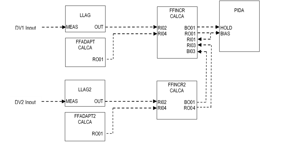
Feedforward control can be implemented for two DVs by adding the following blocks:
- LLAG2 – Applies lag time to the second DV input.
- FFADAPT2 – Calculates adaptive gain for the second DV.
- FFINCR2 – Performs feedforward control for a second DV.
Figure 4 shows how the blocks are combined to provide feedforward control for two DVs.

