
Introduction
Many refining products are blended from various components, some of which are produced by process units in the refinery, and some purchased. The most important of these blended products is usually motor gasoline. Typical gasoline components are:
- Light Straight Run (LSR) naphtha from Crude unit or Naphtha Hydrotreater.
- Cat naphtha from Fluid Catalytic Cracking (FCC) unit.
- Reformate from Reforming unit.
- Isomerate from Isomerization unit.
- Alkylate from Alkylation unit.
- Off-spec gasoline from storage.
- Normal butane from Light Ends unit or purchased.
Gasoline has several specifications that must be met in the blended product, for example:
- Research octane number (RON) indicating knocking likelihood when accelerating.
- Motor octane number (MON) indicating knocking likelihood at constant speed.
- Sulfur composition.
- Reid Vapor Pressure (RVP) indicating tendency to vaporize.
Each specification is usually met by manipulating one of the components that affects the specification to the greatest degree. RON is affected mostly by reformate, MON by alkylate, sulfur by a hydrotreated component, and RVP by butane. In this document, we will describe the strategy employed to control the RVP in a gasoline blend. Other specifications are controlled similarly.
Reid Vapor Pressure (RVP)
Reid Vapor Pressure (RVP) is an ASTM test that measures the volatility of gasoline and other petroleum products. For example, high RVP implies high volatility.
The RVP specification in a gasoline blend will vary throughout the year. In summer, the RVP must be reduced to prevent gasoline from causing vapor lock in the carburetor. In winter, the RVP must be increased to allow sufficient vaporization for starting up in cold weather.
As mentioned above, butane is used to control RVP because it has the greatest effect on RVP. It also is one of the least costly components, so it pays to blend as much butane into the gasoline as the RVP specification will allow.
Blending Control
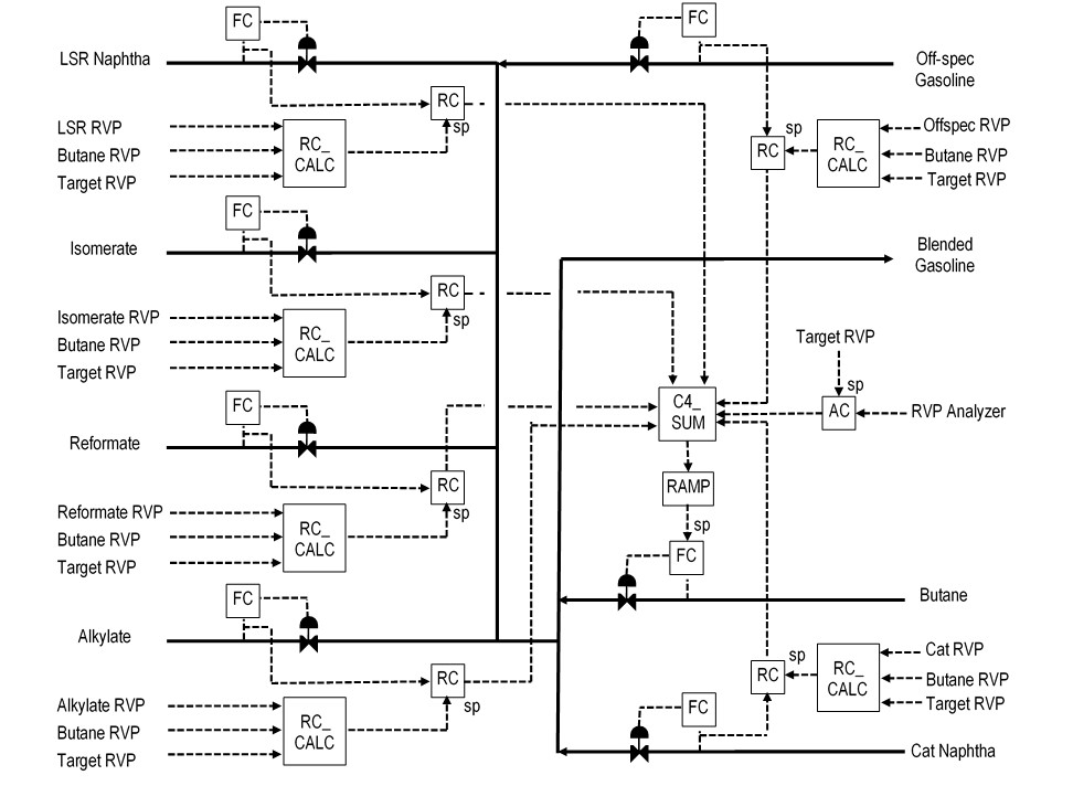
Figure 1 shows a typical blending control scheme. Each component has a flow controller (FC) that sets the component rate to the blend. Each component (except butane) also has a ratio controller (RC) that calculates the butane rate required to achieve the blend target RVP. The RC outputs are summed (C4_SUM), along with a bias correction from an RVP analyzer controller (AC), and the result is sent to the butane FC setpoint.
The butane setpoint is shown going through a “RAMP” block. The ramp ensures a smooth adjustment to the butane FC setpoint whenever component flows vary or RVP entries are changed.
Each RC setpoint must be calculated (RC_CALC) based on the component RVP, the butane RVP, and the blend target RVP. That calculation is described next.
RVP Blending Calculation
RVP is assumed to blend linearly with flow, as shown in the following equation:
RVP = ∑(Fi * RVPi) / ∑Fi (1)
where:
RVP = blend RVP
RVPi = RVP of component i
Fi = flow of component i
For this application, we need to calculate the butane flow ratio for each of the other components:
RVP = (Fb * RVPb + Fi * RVPi) / (Fb + Fi) (2)
where:
RVPb = RVP of butane
Fb = flow of butane
The flow ratio that we are after is calculated as follows:
Ratio = Fb / Fi (3)
Therefore, we must rearrange the terms in equation 2 to permit substituting the term “Ratio”:
RVP * (Fb + Fi) = Fb * RVPb + Fi * RVPi (4)
Dividing both sides of equation 4 by Fi yields:
RVP * (Fb / Fi) + RVP = (Fb / Fi) * RVPb + RVPi (5)
Substituting equation 3, we get:
RVP * Ratio + RVP = Ratio * RVPb + RVPi (6)
Rearranging equation 6, we get Ratio as a function of the component and target RVPs:
Ratio = (RVP – RVPi) / (RVPb – RVP) (7)
Equation 7 is the calculation used in the application to determine the ratio setpoint for each component.
RVP Analyzer Controller
If the gasoline blend has an on-line RVP analyzer, then it can be used to correct the calculation of the total butane required. A continuous analyzer would be the easiest to incorporate into the controls. However, a discontinuous analyzer would present some difficulties for a standard PID controller. Therefore, a model-based predictive controller like the SAS DynaMPC application may be needed. DynaMPC is described in a separate Functional Specification. For the purposes of this document, the RVP is assumed to be continuous, allowing the use of a standard PID controller.
Graphics Support
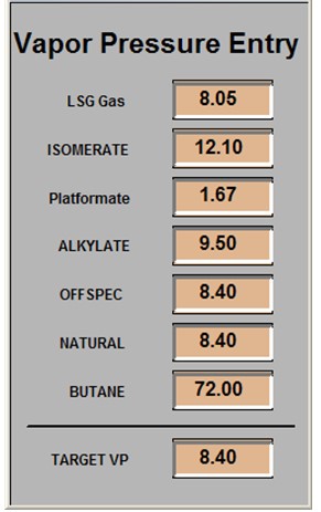
The Gasoline Blending process graphic should include an overlay box to call-up an RVP data entry overlay, such as the one shown in Figure 2. Each RVP entry can be changed by clicking on the value in the overlay, typing the new value, and pressing ENTER. The values should be limited to a reasonable range and be rejected if a value outside of the range is entered.
If it becomes necessary to eliminate a component from the blending calculation, that can be done by typing the target RVP value into the component RVP entry. For example, if the Isom Unit is down, the isomerate flow can be eliminated from the calculations by entering the target RVP into the Isomerate RVP. The ratio controller for the isomerate will then calculate a zero-butane rate even if the isomerate flow is not zero.
FOXBORO I/A IMPLEMENTATION
Foxboro I/A Blocks
The RVP blending control application can be implemented using the following standard blocks:
- RATIO – Performs ratio control (RC) for each of the components.
- CALCA – Performs user-specified calculations and logic to implement the component ratio setpoint calculations (RC_CALC) and the butane summation (C4_SUM).
- LIM – Ramps the input according to an engineer-entered ramp rate.
- PIDA – Provides PID control (FC) for each of the component flows and for the RVP analyzer controller (AC).
Figure 3 shows how the blocks are combined to calculate the butane required for a component. Figure 4 shows the blocks required for control of the butane component.
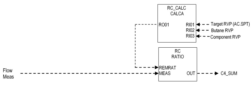
RC_CALC Block
The RC_CALC block performs the following calculation based on equation 7:
RO01 = (RI01 – RI03) / (RI02 – RI01) (8)
The block has the following connections:
RI01 = Blend RVP Target (connect from AC.SPT)
RI02 = Butane RVP
RI03 = Component RVP
The block parameters must be set as follows:
TIMINI = 3
M01 = 0.1
RC_CALC Block Steps
STEP01 = SUB RI01 RI03 ;RVP TARG – COMP RVP
STEP02 = SUB RI02 RI01 ;RVP C4 – RVP TARG
STEP03 = IN M01 ;MIN DIVISOR
STEP04 = MAX 2
STEP05 = DIV
STEP06 = OUT RO01 ;RC REMRAT
STEP07 = END
RC_CALC Block Logic Details
Steps 1-2: Calculate the numerator and the denominator of equation 8.
Steps 3-4: Limit the denominator to a minimum of 0.1 to prevent dividing by zero.
Steps 5-6: Divide the denominator into the numerator and store in RO01.
Ratio Block RC
The RATIO block labelled “RC” requires the following connections:
MEAS = Component flow input.
REMRAT = Ratio setpoint from block RC_CALC.
The block should be locked in auto and remote, so it is forced to use RC_CALC.RO01 as the ratio setpoint:
REMSW = :RC.REMSW.1
AUTSW = :RC.AUTSW.1
The following parameters must be set accordingly:
HSCI1 = Component flow range.
HSCO1 = Butane flow range.
HOLIM = Butane flow range.
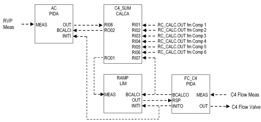
RVP Analyzer Controller AC
The RVP analyzer controller labelled “AC” obtains the RVP from the blend analyzer and adjusts the butane bias input to block C4_SUM. The butane bias can be positive to add butane or negative to subtract butane. The following connections are required:
MEAS = Analyzer RVP input.
BCALCI = Back calculation of the butane bias from block C4_SUM.
INITI = Initialization status from the butane flow controller FC_C4.
The block should be locked in auto and local:
LOCSW = :RC.LOCSW.1
AUTSW = :RC.AUTSW.1
The following parameters must be set accordingly:
HSCO1 = Butane flow range.
LSCO1 = -Butane flow range.
HOLIM = Butane flow range.
LOLIM = -Butane flow range.
INCOPT = 0
Butane Summation Block C4_SUM
The butane summation block C4_SUM obtains the butane calculation values from all component RC blocks, plus the butane bias from the analyzer controller AC, and outputs the sum to the butane ramp block RAMP. This block also performs the back calculation of the butane bias and sends it to the analyzer controller AC. The following connections are required:
RI01 = Component 1 butane calculation from RC.OUT.
RI02 = Component 2 butane calculation from RC.OUT.
RI03 = Component 3 butane calculation from RC.OUT.
RI04 = Component 4 butane calculation from RC.OUT.
RI05 = Component 5 butane calculation from RC.OUT.
RI06 = Component 6 butane calculation from RC.OUT.
RI07 = Back calculation of butane flow from FC_C4.BCALCO.
RI08 = Analyzer controller output AC.OUT.
The block parameter must be set as follows:
TIMINI = 3
Butane Summation Block C4_SUM Steps
STEP01 = ADD RI01 RI02 ;BUTANE COMP 1 + COMP 2
STEP02 = ADD RI03 RI04 ;BUTANE COMP 3 + COMP 4
STEP03 = ADD RI05 RI06 ;BUTANE COMP 5 + COMP 6
STEP04 = ADD 3
STEP05 = OUT RO04 ;SUM OF RC.OUT
STEP06 = ADD RI08 ;AC.OUT
STEP07 = OUT RO01 ;RAMP.MEAS
STEP08 = CST
STEP09 = SUB RI07 RO04 ;RAMP BCALCO – RC.OUT SUM
STEP10 = OUT RO02 ;BCALCO TO AC
STEP11 = END
Butane Summation Block C4_SUM Logic Details
Steps 1-5: Sum all inputs from component RC.OUT blocks and store to RO04.
Steps 6-7: Add the output of analyzer controller AC to the sum in RO04 and store the result to RO01.
Steps 9-10: Perform the back calculation of the butane bias and store to RO02. RO02 is connected to AC.BCALCI.
Butane Ramp Block RAMP
The LIM block labelled “RAMP” requires the following connections:
MEAS = Butane summation block output C4_SUM.RO01.
BCALCI = Butane flow controller FC_C4.BCALCO.
INITI = Initialization status from the butane flow controller FC_C4.INITO.
The block should be locked in auto:
MA = :RAMP.MA.1
The following parameters must be set accordingly:
HSCI1 = Butane flow range.
HSCO1 = Butane flow range.
HOLIM = Butane flow range.
ROCOPT = 1 (Enables ramping).
ROCLIM = Maximum flow change per second.
Butane Flow Controller FC_C4
The butane flow controller labelled “FC_C4” obtains the butane flow and adjusts the butane valve to control the butane flow at the RSP from the RAMP block. The following connections are required:
MEAS = Butane flow input.
RSP = Butane flow from block RAMP.OUT.
The following parameters must be set accordingly:
HSCI1 = Butane flow range.